52
English
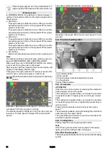
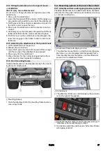
6.4.2 Connections for MIC 70 rear attachment
Note
Fit a dust cap to an unused connection to provide protec-
tion.
1
Electrical PTO
2
Recess (prepared for optional connection)
3
AUX + (A - purple)
4
AUX - (B - purple)
5
Recess (prepared for optional connection)
6
Leakage oil
7
Hydraulic PTO flow (100 litres/min)
8
Hydraulic PTO flow (50 litres/min)
9
Hydraulic PTO return flow
Note
The hydraulic connections AUX are controlled using the
control lever.
Note
The hydraulic PTO is activated using the hydraulic PTO
selector switch in the operating console.
For a description of the selector switch, see chapter
Centre operating console for MIC 70
6.5
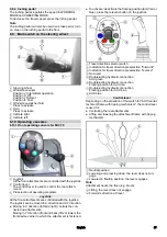
Main switch
1
Main switch
2
Battery disconnected
3
Battery connected
The main switch interrupts the electrical supply line to the
starter motor.
If the main switch is pressed when the engine is running
(battery disconnected), the engine will stop.
Always disconnect the battery when the vehicle is parked.
6.6
Driver cabin
The operator is protected from lightning strikes when sit-
ting in the driver cabin.
The driver cabin has a roll-over protection structure
(ROPS), which prevents rolling over after tipping over.
The driver cabin does not have a structure providing pro-
tection from falling objects (FOPS).
The driver cabin does not have a structure providing pro-
tection from falling objects (OPS).
Always use the safety belt.
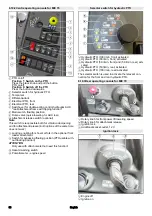
6.6.1 Doors
1
Sliding windows
2
Door handle
3
Ignition key
The driver's door is located at the left side in the travel di-
rection, the emergency exit is located at the right side.
The handle on the B-pillar can be used as an aid for enter-
ing and exiting the cab.
Lock both doors with the ignition key after parking the ve-
hicle.
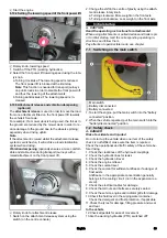
6.6.2 Emergency exit
The emergency exit is located at the right side in the travel
direction.
1
Door handle
Open the emergency exit by pulling the door handle.
Summary of Contents for MIC 70
Page 2: ......
Page 302: ...302 K RCHER K RCHER 2 1 2 2 1 2 3 4 5 6 7 3 REACH www kaercher com REACH 3 1 3 2 4 4 1...
Page 303: ...303 4 2 4 3 4 4 3 4 4 5 DPF 600 C 13 MIC 70 4 6 4 7 4 8...
Page 304: ...304 4 9 10...
Page 305: ...305 4 10 F2 DOT 4 Main fuse 70A F2 3A F2 3A...
Page 310: ...310 1 6 6 4 1 2 3 6 6 5 1 2 0 on 1 on 3 0 1 2 4 5 6 7 8 6 6 6 6 6 7 1 2 3 4 5 6 7 8...
Page 316: ...316 1 Off 2 On 3 6 10 4 1 1 2 a b 6 10 5 1 1 2 a b 7...
Page 318: ...318 7 4 Comfort 1 2 3 4 5 6 7 8 9 10 11 12 13 1 2 3 4 a 7 5 1 2 1 2 3 4 5 7 6 1 2 3 4 8 14...
Page 324: ...324 9 3 9 3 1 3 H 3 2 1 3 2 3 4 5 1 2 9 3 2 3 1 2 3 2 4 1 2 3 1 9 3 3 4 H 4 2 1 4 2 3 4 5 1...
Page 326: ...326 9 4 2 1 2 3 1 9 4 3 1 2 2x 3 1 1 2 9 4 4 3 4 5 9 4 4 1 2 2x 3 4 5 2x 6 1 2 1 2 2x 3 3 4 5...
Page 327: ...327 1 2 3 2x 6 7 1 2x 2 2x 8 9 4 3 9 9 4 5 1 2 1 2 3 4 5 6 7 8 9 9 5 9 5 1 1 1 2...
Page 328: ...328 9 5 2 1 2 16 10 10 1 1 10 2 10 1 1 1 2 3 1 2 3 4 5 6 10 1 2 1 2 10 2...
Page 342: ...342 14 1 MIC 70 14 2 14 3 V2403 CR T EW03 V P0217 5 P0217 Joystick...

