64
English
Note
If the attachment is raised whilst the attachment release
system is switched on, it will act like a load stabilisation
system when driving.
Vibration dampening
(optional) ensures a more comfort-
able and stable drive during transport journeys with a
raised attachment on the front power lift.
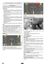
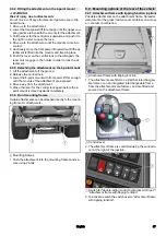
1
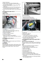
Rotary knob for attachment release
1. Switch on the attachment release system using the
switch (on the centre console).
2. Change the shift in the centre of gravity using the attach-
ment release rotary knob.
a Turning clockwise: More weight on the front axle
b Turning anticlockwise: Less weight on the front axle
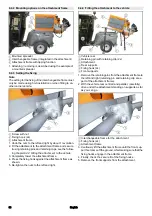
8.5.3 Operating the front power lift
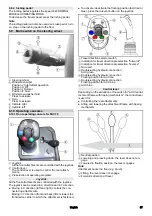
1
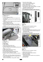
Joystick
1. Pull the joystick backwards (direction Y1) to raise the
front power lift.
2. Push the joystick forwards (direction Y2) to lower the
front power lift.
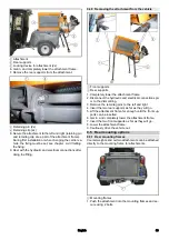
Floating position
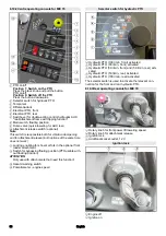
1
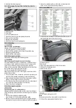
Main switch, floating position
1. The floating position is switched on and off using the
floating position main switch.
The floating position must be switched off when driving
on public roads for transportation purposes (not when
cleaning public roads).
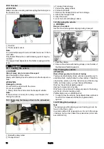
2. Press the joystick in the Y2 direction briefly to switch the
floating position function on. The joystick then returns to
the NEUTRAL position.
In the floating position, the attachment follows the
ground contour.
3. Pull the joystick in the Y1 direction to switch the floating
position function off.
9
Attachments
Note
Please read the attachment operating instructions before
fitting an attachment.
Attachments are optional and can be fitted to the front pow-
er lift (see chapter 8.5 Front power lift) or to the front or rear
mounting frames.
DANGER
Danger due to change to vehicle's centre of gravity
and to driving characteristics. When transporting flu-
ids, sloshing motion may occur, which will then rock
the vehicle.
In the case of modifications, particularly when converting
from winter to summer use and in the case of changes to
load conditions, the driver must be prepared for the
change in driving characteristics.
몇
WARNING
Risk of crushing when attaching attachments
Do not reach between the front power lift and the attach-
ment.
몇
CAUTION
Risk of burns from hot hydraulic couplings
Wear protective gloves when disconnecting the hydraulic
couplings.
ATTENTION
Wear suitable protective clothing, safety gloves and gloves
when installing and removing attachments. This also ap-
plies during usage and application.
Please contact your responsible dealer before fitting at-
tachments that are not specifically intended for this vehi-
cle. Your dealer will check if installation and use of these
attachments is permitted on your vehicle. This is important
for the safety of the driver and the vehicle and also for any
warranty claims.
Attachments that endanger the safety or stability of the ve-
hicle may not be used.
9.1
Coupling attachments to the vehicle
ATTENTION
Risk of damage
Keep hydraulic connections clean.
Clean the plug and coupling with a lint-free cloth before
use.
Summary of Contents for MIC 70
Page 2: ......
Page 302: ...302 K RCHER K RCHER 2 1 2 2 1 2 3 4 5 6 7 3 REACH www kaercher com REACH 3 1 3 2 4 4 1...
Page 303: ...303 4 2 4 3 4 4 3 4 4 5 DPF 600 C 13 MIC 70 4 6 4 7 4 8...
Page 304: ...304 4 9 10...
Page 305: ...305 4 10 F2 DOT 4 Main fuse 70A F2 3A F2 3A...
Page 310: ...310 1 6 6 4 1 2 3 6 6 5 1 2 0 on 1 on 3 0 1 2 4 5 6 7 8 6 6 6 6 6 7 1 2 3 4 5 6 7 8...
Page 316: ...316 1 Off 2 On 3 6 10 4 1 1 2 a b 6 10 5 1 1 2 a b 7...
Page 318: ...318 7 4 Comfort 1 2 3 4 5 6 7 8 9 10 11 12 13 1 2 3 4 a 7 5 1 2 1 2 3 4 5 7 6 1 2 3 4 8 14...
Page 324: ...324 9 3 9 3 1 3 H 3 2 1 3 2 3 4 5 1 2 9 3 2 3 1 2 3 2 4 1 2 3 1 9 3 3 4 H 4 2 1 4 2 3 4 5 1...
Page 326: ...326 9 4 2 1 2 3 1 9 4 3 1 2 2x 3 1 1 2 9 4 4 3 4 5 9 4 4 1 2 2x 3 4 5 2x 6 1 2 1 2 2x 3 3 4 5...
Page 327: ...327 1 2 3 2x 6 7 1 2x 2 2x 8 9 4 3 9 9 4 5 1 2 1 2 3 4 5 6 7 8 9 9 5 9 5 1 1 1 2...
Page 328: ...328 9 5 2 1 2 16 10 10 1 1 10 2 10 1 1 1 2 3 1 2 3 4 5 6 10 1 2 1 2 10 2...
Page 342: ...342 14 1 MIC 70 14 2 14 3 V2403 CR T EW03 V P0217 5 P0217 Joystick...

