DS Series PBX Technical Reference And Installation Guide
191
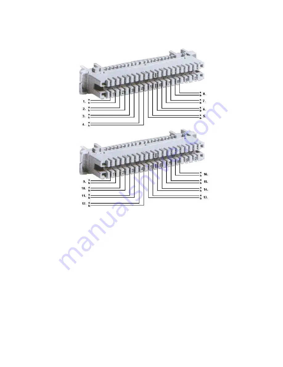
The figure below shows on the photo the arrangement for a cable with 16 pairs, which have
been attached to two patch panels.
The pairs coming from the exchange side are supposed to be attached to the upper section
of patch panel modules, whereas an appropriate multiple installation cable is supposed to be
attached to the lower section and then extended to the external distribution frame.
Regarding cabinet type DS200 installation, the telephone installation cable binders coming
from the external distribution frame are pulled into the cabinet after being passed through the
cable cover on the back. Then, they are pulled to internal distribution frames that are on the
back of racks after they are fixed to the cable carrying stanchion that is on the rear left of the
cabinet.
Summary of Contents for DS200
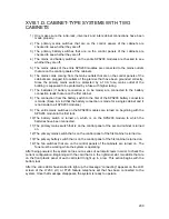
Page 1: ...11 2010 TECHNICAL REFERENCE AND INSTALLATION GUIDE PBX DS SERIES...
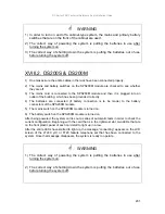
Page 2: ...DS SERIES PBX TECHNICAL REFERENCE AND INSTALLATION GUIDE NOVEMBER 2010...
Page 17: ...DS Series PBX Technical Reference And Installation Guide 7...
Page 69: ...DS Series PBX Technical Reference And Installation Guide 59...
Page 80: ...70...
Page 222: ...11 2010...


