Karel MS128 Installation & Maintenance Guide
Edition 3.2
28
II.4.
DOORPHONE – DY01
MS128 system has a built-in circuitry, which can drive DY01 Doorphone. Any user
of the system can access the doorphone and make a conversation with the party
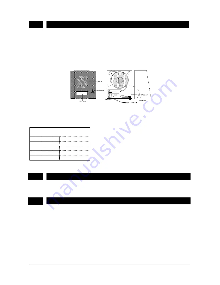
near the doorphone. The voice path is full-duplex. The doorphone has a ring button
on it. This ring button can be utilized to ring an external ringer or an extension
telephone. DY01 doorphone has a speech processor card inside the metal box of
the doorphone.
The outlook and structure of DY01 is illustrated in the following figure.
Figure A-20
The pin-out of the 4-pin RJ socket used to connect DY01 to MS128 CPUKON card
is illustrated in the following table :
MS128 CPUKON Card
Doorphone Connector
Pin no
Signal
1 SPEECH
2 GND
3 +
5
VDC
4 RINGGEN
The dimensions of the DY01 are 12 cm x 14 cm x 3 cm and the weight is 0.5 kg.
II.5.
EXTERNAL ANNOUNCEMENT SYSTEM
Any external announcement system can be connected to MS128 through the 4-pin
RJ socket (the same socket used by DY01 doorphone) on MS128 CPUKON card.
II.6.
AUTO-ATTENDANT & VOICE MAIL - EVM128
EVM128 Auto Attendant guides the external callers throughout their calls with pre-
recorded messages, and hence enables the operator to work more efficiently,
especially under high traffic. Optionally, Voice Mail facilities may be employed, and
then the extensions can have private voice mail boxes to be used to leave / receive
messages to / from other users.
EVM128 has 2 minutes Auto Attendant memory on board. Besides, EVM128 has
two 36-pin connectors on the component side, which are used to install the optional
EVM-FE (Auto Attendant Expansion) and three 24-pin connectors, which are used
to install the optional EVM-DE (Voice Mail Expansion) cards.
Summary of Contents for MS128
Page 1: ...Karel MS128 T e l e p h o n e S y s t e m Installation Maintenance Guide Edition 3 2...
Page 2: ......
Page 6: ......
Page 7: ...TECHNICAL REFERENCE...
Page 8: ......
Page 17: ...Karel MS128 Installation Maintenance Guide Edition 3 2 11 Figure A 7 Figure A 8...
Page 22: ......
Page 42: ......
Page 44: ......
Page 47: ...INSTALLATION GUIDE...
Page 48: ......
Page 50: ......
Page 55: ...Karel MS128 Installation Maintenance Guide Edition 3 2 47 Figure B 4 Figure B 5...
Page 58: ......
Page 85: ...MAINTENANCE GUIDE...
Page 86: ......
Page 89: ......
Page 90: ...Design and specifications subject to change without notice...


