background image

Karel MS128 Installation & Maintenance Guide 
Edition 3.2

71 


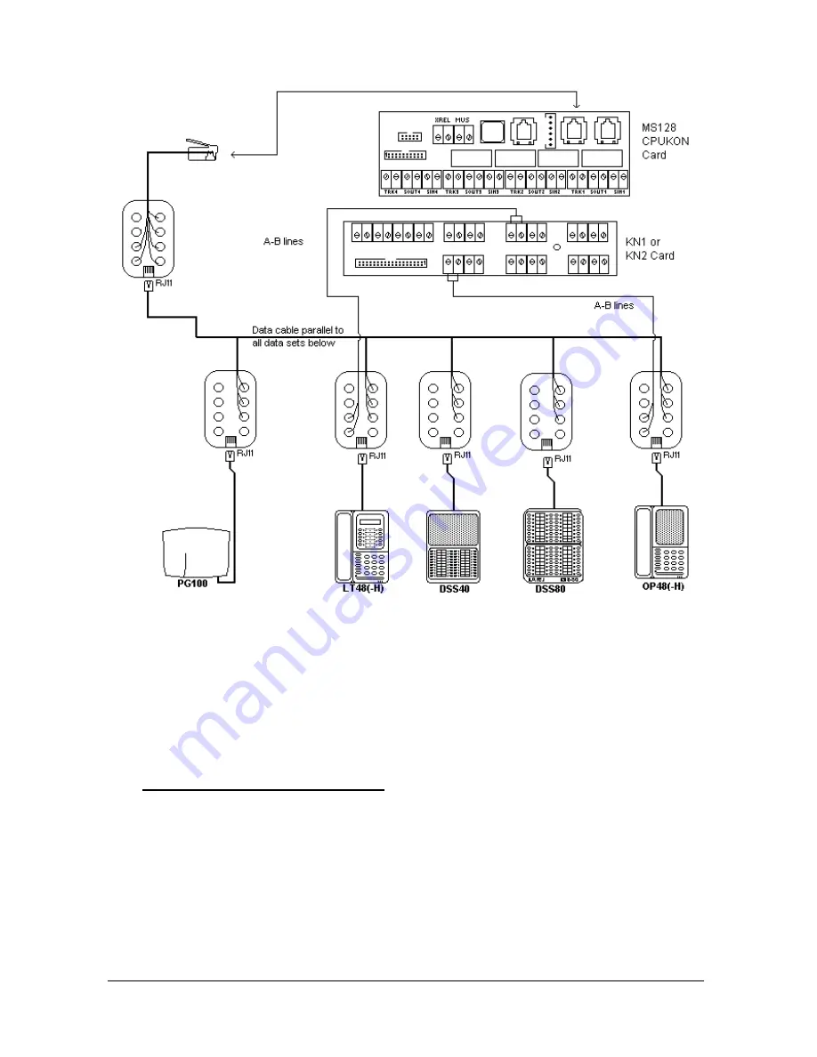
Figure B-28 

The maximum distance between the PG100 Local Pager and the system can be 
300 meters, if the wiring is made with ordinary wires. 

However, the maximum distance of 300 meters decreases proportionally if there 
are KAREL telephones connected to the system. For example, if 2 LT48 
Feature Phones are connected to the system in this way, the distance between 
the system and the PG100 Local Pager cannot exceed 100 meters.  

• 

POWER CONNECTION :


PG100 can be also directly connected to mains voltage through a 12 VDC 
power adaptor. Normally, PG100 receives power over the system data cable. 
However, if the data line of the system is overloaded due to the existence of 
many OP48(-H) and LT48(-H) telephones or DSS40 and DSS80 modules 
connected to the system, it is preferable  to feed PG100 over the power 
adaptor that is to be procured locally. 

The power adaptor can be connected to the PG100 pager via the power socket 
at the bottom part of the PG100 cabinet. 

Summary of Contents for MS128

Page 1: ...Karel MS128 T e l e p h o n e S y s t e m Installation Maintenance Guide Edition 3 2...

Page 2: ......

Page 3: ...P48 H LT48 H DSS80 DSS40 18 II 1 A OP48 H CONSOLE 18 II 1 B LT48 H FEATURE PHONE 20 II 1 C DSS80 DIRECT STATION SELECT MODULE 20 II 1 D DSS40 DIRECT STATION SELECT MODULE 21 II 2 MINI PRINTER KY16 22...

Page 4: ...S FEATURE PHONES DIRECT STATION SELECT MODULES 51 III 2 MINI PRINTER 55 III 3 SERIAL INTERFACE 59 III 3 A PC INTERFACE 59 III 3 B SERIAL PRINTER INTERFACE 60 III 4 DOORPHONE 61 III 5 EXTERNAL ANNOUNCE...

Page 5: ...rence The system outline is given and all the accessories are described Brief information about the software structure of the system is presented and finally the technical specifications of the system...

Page 6: ......

Page 7: ...TECHNICAL REFERENCE...

Page 8: ......

Page 9: ...ower rack a power card a ring transformer and a cable for BPL128 Bacplane connection BPL128 Backplane CPU128 Central Processing Module MS128 EX1 4 12 Expansion Module that can support the minimum capa...

Page 10: ...cabinet provides a strong shell and a natural electromagnetic shield for the system I 1 PARTS LIST In order to make the reader familiar with the cabinet which has a complex structure the parts list f...

Page 11: ...8 Card Slot 9 KN1 KN2 Connection Card Holders 10 Front and Top Cover Holders Female Parts 11 Front and Top Cover Holders Male Parts 12 Pear Holes to hang the system on the wall 13 CPU FC EX FC Flat C...

Page 12: ...right see Figure A 4 One 10 pin male connector for SPS128 Power Supply One 64 pin female connector for CPU128 Central Processing Board Eight 64 pin female connectors for the common use of MS128 EX1 an...

Page 13: ...e first step protection see Figure A 5 The system can operate for the mains input of 180 260 VAC 50 60 Hz which is processed by the SPS128 Power Supply Module I 3 A POWER SUPPLY MODULE SPS128 The fron...

Page 14: ...ngly recommended to use a dry battery for proper operation of the system Also a 24 V 15 Ah battery is recommended for a full capacity system with an average traffic of 35 There exists one F type fuse...

Page 15: ...e below the top cover of CBN128 Cabinet see Figure A 3 It is fixed to the rack by a brass card holder with its screw and two plastic card holders The MS128 CPUKON card is connected to the CPU128 board...

Page 16: ...AG 62 CS8 15 X4 31 GND 47 X6 63 GND 16 5 VDC 32 24 VDC 48 5 VDC 64 24 VDC The data signals for the accessories are generated on CPU128 and then transmitted to MS128 CPUKON via MS128 CPU FC The followi...

Page 17: ...Karel MS128 Installation Maintenance Guide Edition 3 2 11 Figure A 7 Figure A 8...

Page 18: ...bering plan accordingly MS128 EX1 consists of MS128 EX1B and KN1 cards together with the EX FC flat cable Similarly MS128 EX2 includes MS128 EX2B and KN2 cards together with the EX FC flat cable MS128...

Page 19: ...18 SUB9B 27 TRK5A KN2 MS128 EX2B Connector Pin Signal Pin Signal Pin Signal Pin Signal 1 red LED2 10 SUB5A 19 SUB9A 28 SUB14B 2 SUB1A 11 SUB5B 20 SUB10B 29 SUB14A 3 SUB1B 12 SUB6A 21 SUB10A 30 SUB15B...

Page 20: ...10 6 22 X17 38 CS 54 X14 7 CONT2 23 X15 39 DATA 55 X5 8 B 24 X0 40 RD 56 X22 9 DA1 25 X1 41 WR 57 X21 10 DA2 26 X2 42 58 X20 11 A 27 X18 43 DA0 59 X19 12 C 28 X3 44 D 60 X23 13 29 5 VDC 45 61 5 VDC 14...

Page 21: ...ystem to be used for background music facility and to be transmitted to the parties parked or put on hold This connection is established via the 2 pin MUS connector on MS128 CPUKON card I 7 EXTERNAL R...

Page 22: ......

Page 23: ...Guide Edition 3 2 17 II ACCESSORIES To offer you a full telecommunication system MS128 is equipped with many accessories These accessories are shown in the following figure and explained one by one i...

Page 24: ...8 CPUKON Card Telephone DSS Card Console Connector Pin No Signal RJ Socket Pin No 1 12 VDC 6 2 Busy 3 4 5 GND 2 6 Data 1 The input of 12 VDC is regulated to 5 VDC by telephone DSS cards II 1 A OP48 H...

Page 25: ...nance Guide Edition 3 2 19 Handsfree Key Handsfree Volume Adjuster and Handsfree LED are available only on the handsfree versions Figure A 12 Figure A 13 The dimensions of OP48 H are 22 cm x 6 5 cm x...

Page 26: ...48 H Feature Phone is illustrated in the following figure Handsfree Key Handsfree Volume Adjuster and Handsfree LED are available only on the handsfree versions Figure A 14 The dimensions of LT48 H ar...

Page 27: ...as well as some system features DSS40 can be used not only with the MS128 system but also with the other KAREL systems of bigger capacities That is why DSS40 handles 4 digit physical numbers for exte...

Page 28: ...offers Call Record Listing CRL facilities by keeping the records of the external calls and storing them in its non volatile memory against any power failure You may obtain these records by way of som...

Page 29: ...consoles on the MS128 CPUKON card The signaling between the system and KY16 is illustrated in the following table MS128 CPUKON Card KY16 Card Console Connector Pin No Signal Connector Pin No 1 12 VDC...

Page 30: ...ug at the exchange end to be attached to the 9 pin D type plug on the front panel of CPU128 card The software operates under Windows PK128 PC CONSOLE INTERFACE PK128 PC Console is the software which e...

Page 31: ...l 25 pin connector Pin No 9 pin connector Pin No 2 10 VDC 3 2 3 10VDC 2 3 4 TXD 20 4 5 RXD 7 5 7 GND 4 7 The signal names above are given with respect to MS128 system and these pin assignments are val...

Page 32: ...e common pool then this field and the preceding space are not sent to the PC Structure of the second line Starting Character Position Field Width Information 1 8 Date in the format dd mm yy 9 1 Space...

Page 33: ...ctor Pin No 9 pin connector Pin No 2 TXD 3 2 8 RXD 20 4 5 GND 7 5 The signal names above are given with respect to MS128 system and these pin assignments are valid only for IBM compatible devices If y...

Page 34: ...D 3 5 VDC 4 RINGGEN The dimensions of the DY01 are 12 cm x 14 cm x 3 cm and the weight is 0 5 kg II 5 EXTERNAL ANNOUNCEMENT SYSTEM Any external announcement system can be connected to MS128 through th...

Page 35: ...o a certain extent but the difference cannot be recognized by human ear The Voice Mail messages are lost when the system power is off EVM128 supports two voice channels used by both Auto Attendant and...

Page 36: ...result the available ISDN line capacities of MS128 system are illustrated as follows With motherboard only 1 S0 2 analog lines 1 st IA12 ISDN Adaptor With expansion board 2 S0 4 analog lines With mot...

Page 37: ...iple Subscriber Numbering may be active on Point to Multi Point lines These settings are simply managed by the system software The IA12 ISDN Adaptor also supports the following Euro ISDN features prov...

Page 38: ...g The dimensions of EXP IA12 are 9 cm x 8 cm II 8 LOCAL PAGER PG100 PG100 Local Pager lets you page extensions that are equipped with receivers beepers so that they can pick up their calls or attend l...

Page 39: ...the data line of the system is overloaded due to the existence of many OP48 H and LT48 H telephones or DSS40 and DSS80 modules connected to the system it is preferable to feed PG100 over the power ada...

Page 40: ...inst lightning and radio interference KAREL has external modules that can be connected to both extensions and lines These modules are presented in two different models a FPBASE Filter Protection Base...

Page 41: ...stallation Maintenance Guide Edition 3 2 35 Figure A 27 The dimensions of the FPBASE are 18 cm x 12 cm x 3 cm and the weight is 0 4 kg The dimensions of the FPEXP are 17 cm x 12 cm x 2 5 cm and the we...

Page 42: ......

Page 43: ...are facilities which may be activated by any user of the system Operator features are the software facilities which may be activated only by the operator of the system The operator is the first extens...

Page 44: ......

Page 45: ...ncoming external calls 8 MF Receiver Capacity 24 12 x 2 9 Connectors Lines and extensions 623K4 GEO4 type External relay and external music 623K4 GEO4 type External interfaces Pin connectors Tunik RJ...

Page 46: ...500 Hz 300 msec on 300 msec off 300 msec on 300 msec off 300 msec on 2000 msec off 5 Message waiting dial tone 500 Hz 300 msec on 300 msec off 300 msec on 300 msec off 300 msec on 2000 msec off 6 Err...

Page 47: ...INSTALLATION GUIDE...

Page 48: ......

Page 49: ...ges should be reported immediately I 3 ENVIRONMENTAL REQUIREMENTS Before installation the system should be stocked in a place where the temperature is in between 40 C o and 80 C o At start up you shou...

Page 50: ......

Page 51: ...ary information to hang the system on a proper location on the wall that is the bottom drill holes must be 130 cm above the floor To install the system see Figure B 1 1 Place the template on the wall...

Page 52: ...s cable of the system which is equipped with the ground wire Due to this reason it is recommended to operate the system over a mains plug that is properly grounded Checking whether the mains ground is...

Page 53: ...OFF switches must be turned off the SPS128 fixing screws on the system rack must be loosened the power rack must be pulled out and then the cable for BPL128 connection must be removed from SPS128CR To...

Page 54: ...28 comes installed in the cabinet However if it is necessary to take out CPU128 from the cabinet MS128 CPU FC must be removed from CPU128 After that the latch at the top of the plastic card cover must...

Page 55: ...Karel MS128 Installation Maintenance Guide Edition 3 2 47 Figure B 4 Figure B 5...

Page 56: ...cabinet For each KN1 or KN2 card there are one brass and two plastic card holders on the rack top plate To locate the card the top cover of CBN128 cabinet must be opened and then the card must be pla...

Page 57: ...Karel MS128 Installation Maintenance Guide Edition 3 2 49 Figure B 6 IMPORTANT MS128 EX1 and MS128 EX2 cannot be removed from or inserted in the system when the power is on...

Page 58: ......

Page 59: ...the cable can be fixed to the connection box easily The other free end of the cable has also the corresponding RJ socket at the backside of the telephone or DSS module The system itself also comes wit...

Page 60: ...m cabinet and then connected to the console socket on MS128 CPUKON card 2 The Data 12 VDC GND signals on the connection box of the system data cable must be wired in parallel to the corresponding pins...

Page 61: ...a cable to the RJ socket on the connection box of the system data cable FIXING DSS40 DSS80 MODULES TO OP48 H LT48 H Each DSS40 or DSS80 module comes with a plastic telephone connection part used to fi...

Page 62: ...the Data 12 VDC GND and A B ring tip wires of a console or a feature phone are carried separately as described in the Cabling part above the console or feature phone can be installed more than 5 meter...

Page 63: ...ill an extension number is shown on the display Then press the same key several times till the correct extension number appears on the display c DSS80 The setting is made by the A key Press the key ti...

Page 64: ...Printer has a connection box with a cable at its free end The printer end of the data cable is attached to the connection box through a 6 pin RJ plug The cable that comes out of the connection box is...

Page 65: ...onnected to the system the method of cabling for KY16 may be simplified as follows 1 The RJ plug at the end of the cable that comes from the printer must be disconnected from the connection box 2 This...

Page 66: ...lacing the paper roll or the printer ribbon is very easy by way of the mobile front cover of the cabinet To replace the paper roll 1 Pull out the black front cover from the upper side 2 Take out the o...

Page 67: ...le on the bottom cover of the system cabinet the hole below the SPS128 module 2 This 9 pin D type plug must be then connected to the socket on the front panel of CPU128 card 3 The 25 pin D type plug a...

Page 68: ...should be passed through the cable hole on the bottom cover of the system cabinet the hole below the SPS128 module 2 This 9 pin D type plug must be then connected to the socket on the front panel of...

Page 69: ...o the anchor plugs 4 Hang the doorphone on the screws The following figure illustrates the installation Figure B 17 CABLING The cable that emerges from the bottom of the DY01 doorphone has a 6 pin RJ...

Page 70: ...ing button For this 1 Loose the screws at the top and the bottom of the doorphone and open the front cover 2 Loose the screws at the back of the ring button and disconnect the two wire cable between t...

Page 71: ...phone socket on the MS128 CPUKON card The following figure illustrates this installation Figure B 20 MS128 system is enhanced with a facility which provides the efficient use of your amplifier by way...

Page 72: ...gs into the holes 3 Insert the screws into the anchor plugs 4 Hang the adaptor on the screws MOUNTING The IA12 motherboard comes installed in the cabinet It stays on the brass card holders that are at...

Page 73: ...SDN data cable must be attached to the corresponding RJ socket at the bottom part of the IA12 motherboard For the S0 line By the help of a cable having 8 pin RJ45 plugs at both ends the S0 line coming...

Page 74: ...must be connected to line 02 or if the first channel is connected to line 03 the second channel must be connected to line 04 or so on The following figure illustrates the wiring between MS128 system a...

Page 75: ...has a 10 pin connector on the component side of the card This has a correspondent on the MS128 CPUKON card The 10 pin flat cable which comes with EVM128 is used to make the connections between these c...

Page 76: ...B 25 III 8 LOCAL PAGER INSTALLATION The PG100 Local Pager is designed to be mounted on the wall Hence PG100 comes with a template and 2 anchor plugs with screws To install PG100 1 Place the template o...

Page 77: ...d up of two parts One is a cable with a 6 pin RJ plug at both ends and the other one is a connection box The connection box has a 6 pin RJ socket at one side so that one of the free ends of the cable...

Page 78: ...n Select Modules For connecting the PG100 pager to the system 1 The Data 12 VDC GND signals on the connection box of the system data cable must be wired in parallel to the corresponding pins of the co...

Page 79: ...distance between the system and the PG100 Local Pager cannot exceed 100 meters POWER CONNECTION PG100 can be also directly connected to mains voltage through a 12 VDC power adaptor Normally PG100 rece...

Page 80: ...wires of the cable coming from the corresponding line connector on KN1 card and passing through the hole on the side covers of the system cabinet must be attached to the external line The following f...

Page 81: ...stations Figure B 30 III 10 FILTER PROTECTION UNIT INSTALLATION The FPBASE unit has a metal base which has two pear holes Through these pear holes the FPBASE unit can be mounted on the wall On the to...

Page 82: ...is carried to the FPEXP units by way of two washers and a brass card holder see Figure B 32 It should be noted that the directions of the line extension connections are also important The system side...

Page 83: ...ay of its external relay see section III 12 When the power switch of the music source is connected to the relay on the MS128 CPUKON card and the necessary programming is carried on the music source is...

Page 84: ...device Figure B 34 WARNING When the mains power goes off and on if no battery backup is available for the system the external relay may be activated for a very short while which may cause an undesired...

Page 85: ...MAINTENANCE GUIDE...

Page 86: ......

Page 87: ...connector properly c Replace the EVM FE card if any d Replace the EVM128 card e Replace the MS128 CPUKON card 3 No Voice Mail message can be recorded a Check the flat cable connection of the EVM128 c...

Page 88: ...e DY26 doorphone does not function a Check the cabling of the doorphone b Replace the doorphone c Replace the MS128 CPUKON card d Replace the CPU128 card 9 LB or TE is displayed on the consoles and fe...

Page 89: ......

Page 90: ...Design and specifications subject to change without notice...

Reviews: