Karel MS224 Installation & Maintenance Guide
Edition 3.2
12
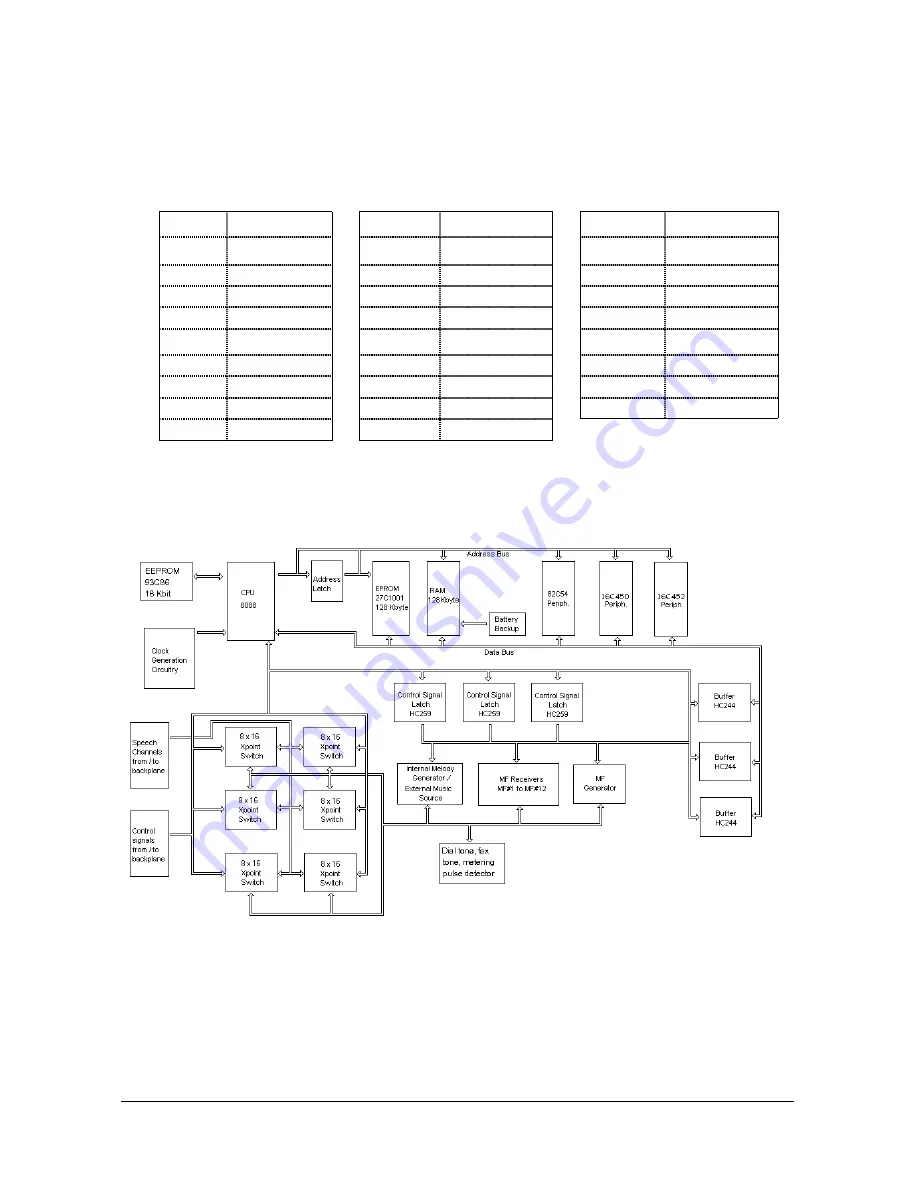
The data signals for all the accessories are generated on CPU224, and then
transmitted to MS224 CPUKON via MS224 CPU-FC. CPU224 also receives the
speech signals - A (ring) / B (tip) - for extension 1111 through the BPL224
backplane and passes them to MS224 CPUKON card via MS224 CPU-FC. The
following table illustrates the pin-out of the MS224 CPU-FC Flat Cable:
MS224 CPU-FC Cable
PIN SIGNAL
PIN SIGNAL
PIN
SIGNAL
1
(red)
XREL2
10
INP1
19
CTS
2 XREL1
11 OUT1
20 +12V
3 MUS1
12 111A
21 OUT2
4 VAG2
13 -24V
22 CM_TXD
5 DIA
14 EMBR
23 CM_RXD
6 GNDCPU
15 SERDATA
24 LEDC
7 +5VCPU
16 EMBT
25 BUSY
8 DIAINP
17 SERISDN
26 111B
9 INP2
18 GNDCPU
There is a LED on the front panel of CPU224 and another one on MS224
CPUKON. During normal operation they blink continuously. During a Reset or a
Parameter Download they remain on. So, the state of the system can be monitored
by way of these LEDs.
Figure A-7
Summary of Contents for MS224
Page 1: ...Karel MS224 T e l e p h o n e S y s t e m Installation Maintenance Guide Edition 3 2...
Page 5: ......
Page 23: ......
Page 43: ......
Page 47: ......
Page 52: ...Karel MS224 Installation Maintenance Guide Edition 3 2 49 Figure B 4 Figure B 5...


