Karel MS224 Installation & Maintenance Guide
Edition 3.2
17
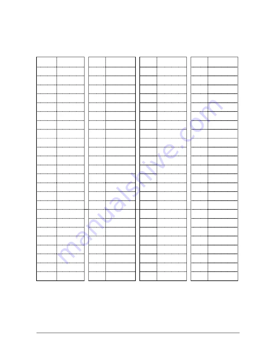
MS224 EX1B and MS224 EX2B cards are connected to the BPL224 Backplane
through the 96-pin connectors on BPL224. The pin-out of the MS224 EX1/EX2 –
BPL224 connector is illustrated in the following table :
MS224 EX1/EX2 – BPL224 Connector
Pin
Signal Pin
Signal Pin
Signal Pin
Signal
1
+ 1 VDC
25
X31
49
X9
73
-
2
- 5 VDC
26
X21
50
X7
74
-
3
CONT3 27
X18 51 GNDCPU 75
-
4
-
28
X16 52
X13 76
-
5
CONT1 29 +
5VDC 53
X5
77
-
6
-
30
RING 54
X2
78
VAG
7
CONT2 31
GND 55
X27 79
-
8
B
32 -24
VDC 56
X24 80 +5
VPU
9
DA1
33
+ 12 VDC
57
X22
81
-
10
DA2 34 -5
VDC 58
X28 82
-
11
A
35
A0
59
X19 83 GNDCPU
12
C
36
A1
60
X17 84
X15
13 SUB1A 37
A2
61 +
5VDC 85
X14
14
VAG 38
CS
62
RING 86
X3
15 X10
39 DATA
63 GND
87
X0
16
+ 5 VCPU
40
RD
64
- 24VDC
88
X25
17
X8 41
WR 65
-
89
X29
18
X6 42
-
66 -
5VDC 90
X30
19 GNDCPU
43
DA0 67 SERISDN
91
X20
20
X12 44
D
68
-
92
-
21
X4 45 SUB1B 69
-
83 +5
VDC
22
X1 46
VAG 70
-
94
RING
23
X26 47
X11 71
-
95
GND
24
X23 48 +
5VCPU 72
-
96 -24
VDC
There is a LED on the front panel of CON1 / CON2 cards. This LED turns on when
any port on the card is in use. During Reset or Parameter Download these LEDs
remain on.
Summary of Contents for MS224
Page 1: ...Karel MS224 T e l e p h o n e S y s t e m Installation Maintenance Guide Edition 3 2...
Page 5: ......
Page 23: ......
Page 43: ......
Page 47: ......
Page 52: ...Karel MS224 Installation Maintenance Guide Edition 3 2 49 Figure B 4 Figure B 5...


