Karel MS224 Installation & Maintenance Guide
Edition 3.2
66
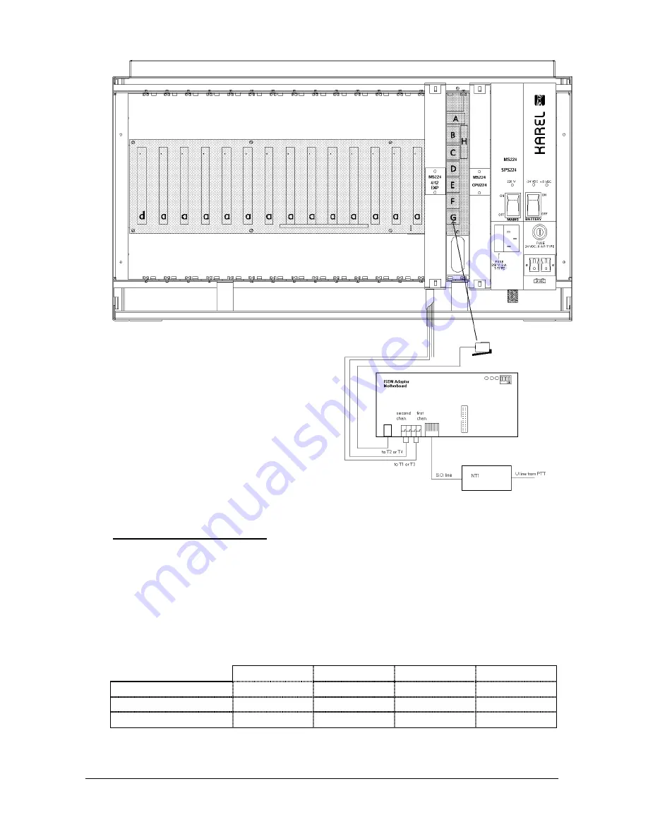
Figure B-20
•
D
IP
-
SWITCH SETTING
:
There exists four dip-switches on the IA12 motherboard, that can be accessed
upon opening the top cover. These dip-switches are used to distinguish the
IA12 ISDN Adaptors connected to the system. For the first adaptor all the dip-
switches must be OFF. For the second one the dip-switch “3” must ON and the
others must be OFF and for the third one (which can have only the IA12
motherboard) the dip-switch "2" must be ON and the others must be OFF. To
make it clear the following table is given:
Dip-switch 1 Dip-switch 2 Dip-switch 3 Dip-switch 4
First Adaptor
OFF OFF OFF OFF
Second Adaptor
OFF OFF ON OFF
Third Adaptor
OFF ON OFF OFF
Summary of Contents for MS224
Page 1: ...Karel MS224 T e l e p h o n e S y s t e m Installation Maintenance Guide Edition 3 2...
Page 5: ......
Page 23: ......
Page 43: ......
Page 47: ......
Page 52: ...Karel MS224 Installation Maintenance Guide Edition 3 2 49 Figure B 4 Figure B 5...


