background image

Karel MS26s

T e l e p h o n e

S y s t e m

Installation

&

Maintenance

Guide

Edition 3.1

Summary of Contents for MS26S

Page 1: ...Karel MS26s T e l e p h o n e S y s t e m Installation Maintenance Guide Edition 3 1...

Page 2: ......

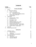
Page 3: ...16 11 II 3 PC INTERFACE CM26s 12 II 4 DOORPHONE DY01 14 II 5 EXTERNAL ANNOUNCEMENT SYSTEM 15 II 6 BATTERY BACKUP UNIT BBU38s 15 II 7 STANDARD TELEPHONE SETS LADIN FULYA 17 II 8 FILTER PROTECTION UNIT...

Page 4: ...II 3 PC INTERFACE 42 III 4 DOORPHONE 43 III 5 EXTERNAL ANNOUNCEMENT SYSTEM 46 III 6 BATTERY BACKUP UNIT 46 III 7 STANDARD TELEPHONE SETS EXTERNAL LINES 49 III 8 FILTER PROTECTION PROTECTION UNITS 49 I...

Page 5: ...rence The system outline is given and all the accessories are described Brief information about the software structure of the system is presented and finally the technical specifications of the system...

Page 6: ......

Page 7: ...TECHNICAL REFERENCE...

Page 8: ......

Page 9: ...extensions The system consists of the following parts CBN26s Cabinet made of plastic MB26s Motherboard PS38 Power Adaptor including a plastic cabinet called PS38CB and a power card called PS38CR See t...

Page 10: ...A 2 I 1 MB26s MOTHERBOARD The MB26s motherboard consists of the microprocessor utility DTMF switching line and extension circuitries See the following figures for the location of these circuitries an...

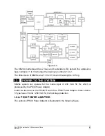
Page 11: ...f MB26s are 21 cm x 23 cm and the weight is 0 35 kg I 2 POWER TO THE SYSTEM MS26s system can operate for the mains input of 230 VAC 50 Hz which is processed by the PS38 Power Adaptor Inside the fuse s...

Page 12: ...is also regulated to 5 VDC by the MB26s motherboard PS38 Power Adaptor can be directly plugged in the mains socket on the wall The connection to the system is established via the built in cable that i...

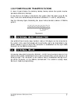
Page 13: ...3 EXTERNAL MUSIC CONNECTOR Any external music source tape recorder radio or CD player can be connected to the system to be used for background music facility and to be transmitted to the parties park...

Page 14: ......

Page 15: ...e Guide Edition 3 1 9 II ACCESSORIES To offer you a full telecommunication system MS26s is equipped with many accessories These accessories are shown in the following figure and explained one by one i...

Page 16: ...nsion line or calling a Private Pool number by the help of the 10 programmable keys in the upper keypad The outlook of LT26s H Handsfree Feature Phone is illustrated in the following figure Handsfree...

Page 17: ...some external devices One of these external devices is KY16 Mini Printer which gives 16 column printout using an Epson type print head The following figure illustrates the outlook of KY16 Mini Printe...

Page 18: ...Call Record Listing CRL Interface for PC connection Call records which are transferred to the PC via the serial communication port on MB26s motherboard are processed by the CM26s CRL software A 3 5 di...

Page 19: ...lid only for IBM compatible devices If your device is not IBM compatible then you must provide the requested pin connections to match the signaling parameters of the system The communication protocol...

Page 20: ...be connected to the system at a time The selection among these devices is made by programming II 4 DOORPHONE DY01 MS26s system has a built in circuitry which can drive DY01 Doorphone Any user of the s...

Page 21: ...used by DY01 doorphone on MB26s motherboard II 6 BATTERY BACKUP UNIT BBU38s BBU38s is a stand alone power supply module enhanced with battery backup circuitries BBU38s contains two separate boxes cal...

Page 22: ...ckup Module has a built in mains cable which is to be attached to the mains socket The module has another built in cable with an 8 pin RJ plug at the end which is to be connected to the corresponding...

Page 23: ...BU38s is also capable of charging the battery while the system power is on and the system is running under low traffic Besides there exists a low voltage battery cut off circuitry which turns itself o...

Page 24: ...on 3 1 18 Figure A 13 The following figure illustrates the outlook of Fulya Figure A 14 The dimensions of the Ladin are 22 cm x 6 5 cm x 15 5 cm and the weight is 0 6 kg The dimensions of the Fulya ar...

Page 25: ...base cover which exists only on FPBASE unit FPEXP units are installed on top of an FPBASE unit So if a Filter and Protection Unit is required for a system then an FPBASE unit must be used and dependi...

Page 26: ...of handling four lines or extensions The difference between SPBASE and SPEXP is the base cover which exists only on SPBASE SPEXP units are installed on top of an SPBASE unit So if a Protection Unit i...

Page 27: ...erator features 3 Programs User features are the software facilities which may be activated by any user of the system Operator features are the software facilities which may be activated only by the o...

Page 28: ......

Page 29: ...ry Backup with 12 VDC Power failure transfer stations 5 Dialing Dial Pulse DP 10 pps Dual Tone Multifrequency DTMF 140 msec 6 Dialing conversions DP DTMF DTMF DP 7 Speech paths 8 Nonblocking 8 MF Rece...

Page 30: ...0 45 C 0 20 80 Humidity 12 Hook flash Duration Range 100 600 msec 13 Dimensions 28 cm x 5 cm h x 25 cm 14 Weight 0 8 kg 15 Maintenance Built in Self Diagnosis On Site Remote Programming PC Console TON...

Page 31: ...enance Guide Edition 3 1 25 DTMF tones High frequency group 7 dBm 1209 Hz 1336 Hz 1477 Hz Low 697 Hz 1 2 3 frequency 770 Hz 4 5 6 group 852 Hz 7 8 9 9 dBm 941 Hz 0 Nominal frequencies of MS26s may dev...

Page 32: ......

Page 33: ...INSTALLATION GUIDE...

Page 34: ......

Page 35: ...tely I 3 ENVIRONMENTAL REQUIREMENTS Before installation the system should be stocked in a place where the temperature is in between 40 C o and 80 C o At start up you should make sure that the room whe...

Page 36: ......

Page 37: ...he wall The template also has the necessary information to hang the system on a proper location on the wall that is the top drill hole must be 150 cm above the floor To install the system 1 Place the...

Page 38: ...Karel MS26s Installation Maintenance Guide Edition 3 1 30 Figure B 2 Figure B 3 6 Hang the cabinet on the wall by placing the two pear holes at the back of the cover over the screws see Figure B 4...

Page 39: ...sions lines accessories and power adaptor is completed IMPORTANT The equipment can be installed only by the service personnel The area behind the front cover is not for operator access hence the front...

Page 40: ...se better to construct an ideal ground simply by inserting a metal bar of at least 1 5 m length and 1 5 cm radius copper is preferable into the earth as illustrated in the following figure Figure B 5...

Page 41: ...is necessary to take out the MB26s motherboard from the cabinet the holder at the bottom must be pressed and the card must be removed see Figure B 5 To insert MB26s back in the cabinet the upper side...

Page 42: ...Karel MS26s Installation Maintenance Guide Edition 3 1 34 Figure B 7...

Page 43: ...one is a connection box The connection box has a 6 pin RJ socket at one side so that one of the free ends of the cable can be fixed to the connection box easily The other free end of the cable has al...

Page 44: ...on 11 5 Busy 6 8 VDC Note Busy signal is for KY16 Mini Printer Figure B 9 The following signals are present on the connection box of telephone data cable 1 Data Signal 2 Ground GND 3 A ring signal fro...

Page 45: ...tem data cable must be wired in parallel to the corresponding pins of the connection box of the telephone data cable 3 The RJ plug at the free end of the telephone data cable must be inserted into the...

Page 46: ...e carried separately as described in the Cabling part above the feature phone can be installed more than 5 meters away from the system In such a case the maximum distance between a single feature phon...

Page 47: ...t at a height of 150 cm 2 Drive the anchor plugs into the holes 3 Insert the screws into the anchor plugs 4 Hang the printer on the screws The following figure illustrates the installation Figure B 12...

Page 48: ...Feature Phones as well must be wired in parallel to the corresponding pins of the connection box of the printer data cable see Figure B 13 In the absence of LT26s H Feature Phones connected to the sys...

Page 49: ...KY16 cabinet must be set as follows Dip switch Position 1 OFF 2 OFF 3 ON 4 ON PAPER ROLL PRINTER RIBBON Replacing the paper roll or the printer ribbon is very easy by way of the mobile front cover of...

Page 50: ...e end of the PC Exchange cable must be passed through the cable holes at the bottom part of the cabinet and connected to the CM socket on the MB26s motherboard 2 The 25 pin D type plug at the other en...

Page 51: ...related programming code for selecting the PC as the CRL Call Record Listing media as explained in the MS26s Programming Guide III 4 DOORPHONE INSTALLATION DY01 Doorphone is designed to be mounted on...

Page 52: ...m the bottom of the DY01 doorphone has a 4 pin RJ plug at its free end For connecting the doorphone to the system this plug must be passed through the cable holes at the bottom part of the cabinet and...

Page 53: ...s 1 Loose the screws at the top and the bottom of the doorphone and open the front cover 2 Loose the screws at the back of the ring button and disconnect the two wire cable between the doorphone card...

Page 54: ...strates this installation Figure B 20 III 6 BATTERY BACKUP UNIT INSTALLATION BBU38s Battery Backup Unit is designed to be mounted on the wall Hence BBU38s comes with a template and 4 anchor plugs with...

Page 55: ...he battery box below the special battery holder 3 Connect the battery to the connector on BBU38s card paying special attention to the polarity see Figure A 12 The cable for battery connection must go...

Page 56: ...38s 1 The 8 pin RJ plug at the free end of the power cable for system connection must be passed through the cable holes at the bottom part of the cabinet and connected attached to the POWER socket on...

Page 57: ...n be connected as much as 2 km away from the system by using ordinary copper wires Depending on the quality of the wires the distance changes proportionally III 8 FILTER PROTECTION PROTECTION UNITS IN...

Page 58: ...he FPEXP SPEXP units by way of the two washers and a brass card holder see Figure B 31 It should be noted that the directions of the line extension connections are also important The system side of th...

Page 59: ...e 2 pin MUS connector on the MB26s motheboard as illustrated in the following figure Figure B 26 III 10 EXTERNAL RELAY The relay on the MS26s motherboard can be used to switch one of the following equ...

Page 60: ...Karel MS26s Installation Maintenance Guide Edition 3 1 52 Figure B 27...

Page 61: ......

Page 62: ...Design and specifications subject to change without notice...

Reviews: