Karel MS26s Installation & Maintenance Guide
Edition 3.1
20
II.9.
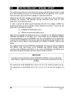
PROTECTION UNIT – SPBASE, SPEXP
The external lines that are connected to the system and the extension lines coming
from other buildings are open to environmental effects like lightning. Also, in some
instances there may be 220 VAC leakage to extensions and lines.
Although the 220 VAC leakage through lines is not risky due to the transformers
employed for isolation, the leakage through extension ports may be quite
destructive for the DS200 system.
In order to protect the system against lightning and 220 VAC leakage, KAREL has
external units that can be connected to both extensions and lines. These units are
presented in two different models:
a) SPBASE Protection Base Unit
b) SPEXP Protection Expansion Unit
Both units are capable of handling four lines or extensions. The difference between
SPBASE and SPEXP is the base cover, which exists only on SPBASE. SPEXP
units are installed on top of an SPBASE unit. So, if a Protection Unit is required for
a system then an SPBASE unit must be used and depending on the capacity of the
ports that must be filtered and protected, any number of SPEXP units can be
added.
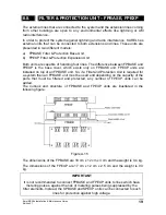
The outlook and structures of SPBASE and SPEXP units are the same as FPBASE
and FPEXP units (see Figure A-15). SPBASE and SPEXP employ different
circuitries than FPBASE and FPEXP, in the sense that SPBASE and SPEXP units
have fuses instead of inductors and they have no filters on board.
IMPORTANT
It is highly recommended to connect SPBASE and SPEXP units to extensions,
which may be subject to 220 VAC leakage or to the extensions going out of the
building.
The dimensions of the SPBASE are 18 cm x 12 cm x 3 cm and the weight is 0.4 kg.
The dimensions of the SPEXP are 17 cm x 12 cm x 2.5 cm and the weight is 0.3
kg.
Summary of Contents for MS26S
Page 1: ...Karel MS26s T e l e p h o n e S y s t e m Installation Maintenance Guide Edition 3 1...
Page 2: ......
Page 6: ......
Page 7: ...TECHNICAL REFERENCE...
Page 8: ......
Page 14: ......
Page 28: ......
Page 32: ......
Page 33: ...INSTALLATION GUIDE...
Page 34: ......
Page 36: ......
Page 42: ...Karel MS26s Installation Maintenance Guide Edition 3 1 34 Figure B 7...
Page 60: ...Karel MS26s Installation Maintenance Guide Edition 3 1 52 Figure B 27...
Page 61: ......
Page 62: ...Design and specifications subject to change without notice...


