Karel MS26s Installation & Maintenance Guide
Edition 3.1
38
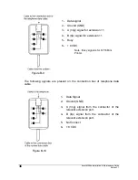
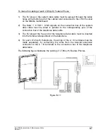
In case the operator’s LT26s(-H) Feature Phone is located near the system, the
method of cabling may be simplified as follows :
1) The RJ plug on the system data cable must be passed through the cable
holes at the bottom part of the cabinet and connected to the LT/OP socket
on the MB26s motherboard.
2) The connection box must be removed from the telephone data cable.
3) One of the RJ plugs on the telephone data cable must be attached to the
RJ socket on the connection box of the system data cable.
4) The other RJ plug at the free end of the telephone data cable must be
inserted into the female correspondant on the telephone.
5) In such a case there is no need to make a separate wiring for the A / B
terminals either, as the system data cable is designed to carry the A / B
signals for the operator.
•
D
ISTANCE OF TELEPHONES TO THE SYSTEM
:
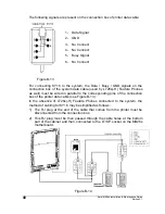
If the Data / 8 VDC / GND and A / B (ring / tip) wires of a feature phone are
carried separately as described in the “Cabling” part above, the feature phone
can be installed more than 5 meters away from the system.
In such a case, the maximum distance between a single feature phone and the
system can be 250 meters, if the wiring is made with ordinary wires.
However, if more than one set
will be installed to the system and if the Data / 8
VDC / GND wires of the sets are wired in parallel as described in the “Cabling”
part above, the maximum distance of 250 meters decreases proportionally. For
example, if 5 LT26s(-H) Feature Phones are connected to the system in this
way, the distance between the system and the LT26s(-H) Feature Phones
cannot exceed 50 meters.
In such a case, the performance can be further improved by conn8
VDC power supply, if the data voltage of the ultimate console is below 7.5 VDC,
between 8 VDC and GND terminals.
•
E
XTENSION NUMBER SETTING
:
After the wiring of LT26s(-H) Feature Phones, the extension setting of these
sets should be made by the "H/R" key. Keep the key pressed till an extension
number is shown on the display. Then, press the same key several times till the
correct extension number appears on the display.
Summary of Contents for MS26S
Page 1: ...Karel MS26s T e l e p h o n e S y s t e m Installation Maintenance Guide Edition 3 1...
Page 2: ......
Page 6: ......
Page 7: ...TECHNICAL REFERENCE...
Page 8: ......
Page 14: ......
Page 28: ......
Page 32: ......
Page 33: ...INSTALLATION GUIDE...
Page 34: ......
Page 36: ......
Page 42: ...Karel MS26s Installation Maintenance Guide Edition 3 1 34 Figure B 7...
Page 60: ...Karel MS26s Installation Maintenance Guide Edition 3 1 52 Figure B 27...
Page 61: ......
Page 62: ...Design and specifications subject to change without notice...


