10
NL
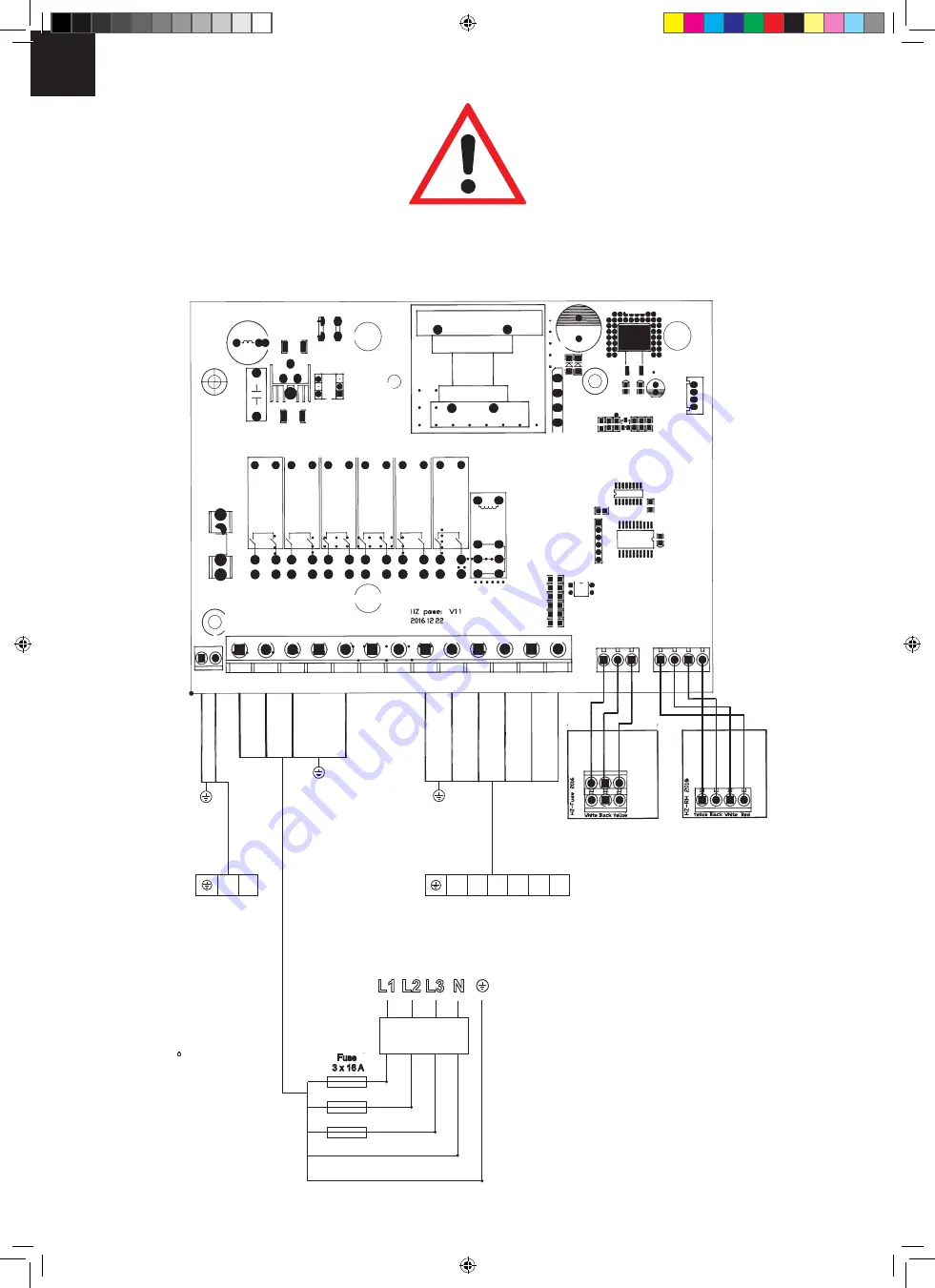
9.1 Schéma zapojení STG 2100 - FH
Rot/Red
schwarz/black
weiss/white
gelb/yellow
schwarz/black
weiss/white
gelb/yellow
weiss/white
schwarz/black
gelb/yellow
Rot
schwarz
weiss
gelb
Lampe
Light
N
N
N
N W V U WB WM
W1
L3
L2
L1
N L
V
U
WB
WM
Klemmleiste Saunaofen
Terminal block sauna heater
N
L
Sicherung
Fuse
3 x 16 A
7 x 1,5 mm²
3 x 1 mm²
N
W
N
L3
L2
L1
Fehlstromschalter
non operate switch
FI - 25A/0,03A
5 x 2,5 mm²
1
2
Schaltplan
STG 2100-FH
wit/white
zw
ar
t/black
geel/y
ello
w
wit/white
zw
ar
t/black
geel/y
ello
w
rood/r
ed
wit/white
zw
ar
t/black
geel/y
ello
w
geel/y
ello
w
wit/white
zw
ar
t/black
rood/r
ed
Lamp
Differentiaaluitschakelaar
Contactstrip saunakachel
Schaltplan
STG 2100-FH
Zekering
ISC_STG2100_Anleitung_NL.indd 10
10.08.17 08:21
Summary of Contents for 2541
Page 5: ...01 4 70 Ø3 mm 10x B 14 B 16 C 2 C 4 C 6 2x 1029 mm 1662 mm 1492 mm 858 mm 2x 90 ...
Page 6: ...02 W 2 W 4 4 5 80 Ø4 mm 10x B 17 ...
Page 7: ...03 04 4 5 80 Ø4 mm 10x B 1 W 5 W 5 B 1 B 1 B 17 B 17 B 17 ...
Page 8: ...05 4 5 80 Ø4 mm 10x W 3 W 1 B 17 B 17 B 17 ...
Page 9: ...06 4 5 80 Ø4 mm 10x K 1 K 1 R 1 R 1 4 5 40 Ø4 mm 4x ...
Page 14: ...M 2 M 1 B 1 3x 6x 3x 3x 3x 4 70 Ø3 mm 18x 11 ...
Page 15: ...12 4 5 40 Ø4 mm 33x B 8 B 7 B 9 B 4 G 2 G 2 G 2 G 2 B 4 ...
Page 16: ...13 4 5 40 Ø4 mm 4x ...
Page 18: ...6 60 Ø5 mm 5x B 11 B 12 500 mm 800 mm 15 B 2 B 2 545 mm 45 mm 6 60 Ø5mm 24x 4 50 Ø3mm 8x 1 2 ...
Page 20: ...18 Übersicht Overview enquête overzicht undersøgelse estudio sondaggio přehled L 2 L 1 ...
Page 24: ...23 1 2 3 ...
Page 25: ......
Page 26: ......
Page 27: ......
Page 28: ......
Page 29: ......
Page 30: ......
Page 31: ......
Page 32: ......
Page 33: ......
Page 34: ......
Page 35: ......
Page 36: ......
Page 37: ......
Page 38: ......
Page 39: ......
Page 40: ......
Page 41: ......
Page 42: ......
Page 43: ......
Page 44: ......
Page 45: ......
Page 46: ......
Page 47: ......
Page 48: ......
Page 49: ......
Page 50: ......
Page 51: ......
Page 52: ......
Page 53: ......
Page 54: ......
Page 55: ......
Page 56: ......
Page 57: ......
Page 58: ......
Page 59: ......
Page 60: ......
Page 61: ......
Page 62: ......
Page 63: ......
Page 64: ......
Page 65: ......
Page 66: ......
Page 67: ......
Page 68: ......
Page 69: ......
Page 70: ......
Page 71: ......
Page 72: ......
Page 73: ......
Page 74: ......
Page 75: ......
Page 76: ......
Page 83: ...D 6 0 Wandmontage Steuergerät 2 Stück Schrauben 4 x 25 mm 1 Stück Schraube 4 x 25 mm ...
Page 89: ...D 080 000 000 020 000 000 OFF 70 OFF 70 Einstellung Beleuchtung ...
Page 97: ...D 13 0 Explosionszeichnung STG 2100 F STG 2100 F Art Nr 37 470 01 I Nr 18012 ...
Page 98: ...D 13 1 Stückliste STG 2100 F I Nr 18012 ...
Page 99: ...D STG 2100 FH Art Nr 37 470 11 I Nr 18012 13 2 Explosionszeichnung STG 2100 FH ...
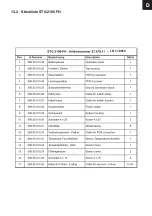
Page 100: ...D 13 2 Stückliste STG 2100 FH I Nr 18012 ...
Page 101: ...D ...
Page 104: ...D ...
Page 159: ...ISC_STG2100_Anleitung_F indd 28 10 08 17 08 14 ...

