Note:
The control equipment may be destroyed even if it is incorrectly connected
only once. The warranty will be voided if the electrical connection is not
correct.
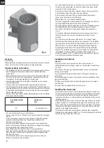
Instructions for the electrician
DIN VDE 0100 and Accident Prevention Regulation BGV A2 must be observed
for connecting the stove and all electrical systems. An external all-pole
disconnecting device with full isolation according to overvoltage category III must
be installed.
Important:
Mains connection leads must be
À
exible cables with polychlorophene sheaths.
No connection leads are supplied with the stove. All the cables installed inside
the cabin must be capable of withstanding temperatures of at least 140 °C.
Heat-resistant silicon cables must be used. The minimum cross-section of the
connection cable and the minimum size of the sauna cabin are shown in the
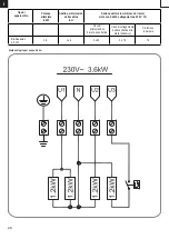
table (page 5 Table 1). A connection diagram is af
¿
xed to the inside of the duct
cover. Please note that for safety reasons live cables are not allowed to be routed
visibly along the internal walls of the cabin. In prefabricated sauna cabins the wall
element with the air supply opening generally has empty cable conduits or a duct
for routing the cable. If your cabin does not have any cable routing preparations,
we recommend that you install a connection socket (not supplied) to the outside
of the cabin. Drill a hole in the cabin wall near the cable infeed from the stove
and the connection socket. Thread the cable through the hole to the external
connection socket. All cables must be protected from damage. This can be
achieved using installation ducting/piping or using wooden covers.
Test the insulation resistance
The resistance values between the various conductor terminals and the case
(protective earth) can be measured using an insulation resistance measuring
unit. The total insulation resistance between the conductor terminals and case
(protective earth) must de
¿
nitely be greater than 1 MOhm.
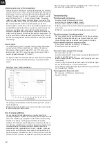
Ohm values of the stoves
9
GB
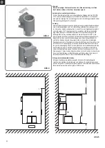
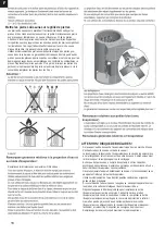
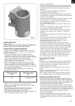
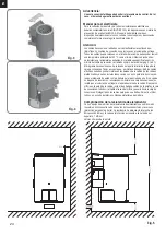
Fig. 3
Fig. 4
Fig 5
Anleitung_ Bio-Saunaofen_37.467.12.indd 9
Anleitung_ Bio-Saunaofen_37.467.12.indd 9
24.06.15 18:42
24.06.15 18:42
Summary of Contents for 75260
Page 8: ...15 1 Ø3mm 13 13 1 13 1 15 14 Ø3mm 4x70 3x 4x 4 70 14x 4x70 B 1 M 1 M 1 15 1 ...
Page 22: ...01 01 1 A 2 A 3 02 01 1 02 1 02 1 A 1 4 50 Ø3mm 4 40 Ø3mm 4 40 Ø3mm 4 50 8x 4 40 8x 4 50 Ø3mm ...
Page 23: ...03 04 60mm 06 05 07 08 D 2 4 5 40 Ø3mm D 1 60mm 4 5 40 8x ...
Page 24: ...Karibu Artikel Nr Artikel Nr I Nr Typ 70444 37 467 12 15011 Bio Saunaofen 3 6 kW ES SS P P ...
Page 25: ...2 Mettre les pierres du sauna sur la grille de pierres ...
Page 54: ...NL Vul het reservoir met maximaal 2 liter water 31 ...
Page 61: ...38 Ersatzteilzeichnung 1 2 3 4 5 6 7 8 9 10 11 12 13 ...
Page 73: ...8 8 B H F 3 3 3 3 B H P B H B H P 1 P B H 1 1 B H 8 1 1 3 B H F F 1 H F 1 F 3 3 3 ...
Page 74: ... ISC GmbH Art Nr 086 50 009 93 15011 Stand 04 2015 ...
Page 207: ...WORLD OF WELLNESS NOTIZEN APPUNTI NOTES NOTE NOTITIES ...
Page 208: ...WORLD OF WELLNESS NOTIZEN APPUNTI NOTES NOTE NOTITIES ...
Page 209: ...WORLD OF WELLNESS NOTIZEN APPUNTI NOTES NOTE NOTITIES ...


