23
GB
4.0 - General information and instructions
on sauna usage
4.1 - Sauna cabin – sauna heater - sauna
controller
The FIN and BIO control units are an integral
part of a well-functioning sauna cabin, as
long as all the necessary condition s are
properly met.
A control unit can only work to optimum
effect in combination with a suitable sauna
heater if the electrical connections from the
main distributor to the control unit and from
the control unit to the sauna heater have
been installed correctly and professionally
in accordance with our circuit diagrams and
speci
fi
cations using the materials intended
for the purpose.
Faults on the control unit may also be caused
by insuf
fi
cient incoming air or insuf
fi
cient
ventilation of the sauna heater, as well as by
a lack or waste air vents or waste air vents
that are too small when the sauna is used
continuously. In this connection, please
refer to and observe our “Information sheet”
which is also included.
With regard to the temperature and humidity
settings, discrepancies between the set
and displayed temperature and humidity
are possible. This can be explained by the
fact that the mechanical display units are
generally installed on the inside wall of the
sauna. The temperature of the sauna wall,
however, is always lower than that of the
actual air temperature in the cabin.
The displayed humidity levels can be
incorrect at the start for as long as the cabin
has not heated up enough to a suf
fi
cient
temperature.
5.0 – General safety instructions
5.1 - Proper use
The FIN and BIO control units are designed
only for use for the control of sauna heaters
with a maximum output of up to 10.80 kW.
The FIN control unit is for sauna heaters
with Finnish mode (temperature control
only) and the BIO control unit can be used
for bio mode (temperature and humidity).
The control unit is designed to be used
in sauna cabins which are suitable for the
purpose! The control unit is only suitable for
the operation of approved sauna heaters
and in sauna cabins which are suitable for
the purpose.
The control units are designed for operation
in private households only!
Any claims for compensation for damages
arising out of or in connection with improper
use are excluded.
The user or operator will be exclusively
responsible for any damages resulting from
such improper use.
5.2 - Installation and electrical
connection
The control units must be correctly installed
in accordance with the supplied installation
instructions and connected up to the
electricity supply in accordance with the
enclosed circuit diagram.
Only a quali
fi
ed electrician or an electrical
contractor may make the electrical
connection from the main distributor in the
residential building to the control unit and
from the control unit to the sauna heater.
The system must be
fi
tted with a separate
residual current device circuit-breaker
(earth leakage circuit breaker 40A 30mA).
Refer to the safety actions required by VDE
100 Section 49 DA/6 and VDE 0100 Part
703/11.82 Section 4.
Summary of Contents for Sauna 280
Page 1: ...Sauna 280...
Page 5: ...Sauna 280 1 4xM 4xM DET 1 2xDET A 1600 2100 mm mm DET 1...
Page 6: ...Sauna 280 2 I 1x DET 2 II 2 3a 3b 4 x DET 3a 4 x DET 3b 2x M X Z W Y 100 600 mm mm...
Page 7: ...Sauna 280 3 I II 16x M...
Page 8: ...Sauna 280 90 2x DET P 3A Bohren Sie 4 L cher in DET 2 10 mm...
Page 9: ...4 II I 3x I 3x I 4a 4b 4e 4f R ckwand Vorderwand R ckwand Vorderwand SAUNA 280...
Page 11: ...6 I II 11x DET 3b 10x DET 3a 8x DET 3a 8x DET 3b 16xH 16xH 20xH Siehe Seite 6A SAUNA 280...
Page 15: ...Sauna 280 9 2xDET F 1xDET G 1xDET F 3x K 3x K 3x K 3x K...
Page 16: ...Sauna 280 10 4x DET 7 12x H 575 I II 2xDET 8...
Page 17: ...Sauna 280 4xDET 9 4x H Bitte bohren Sie 4mm L cher vor dem festschrauben 4x H 11 4x H 770...
Page 21: ...Sauna 280 15 4x M 3x H 2xDET 19 2xDET 18 2x M 3x H...
Page 22: ...Sauna 280 16 I 10x H mm mm 2xDET 20 II 14xDET 21 28x H III Entfernen DET A...
Page 76: ...32...
Page 84: ...ISC GmbH Art Nr 086 50 009 23 11011 Stand 05 2020...
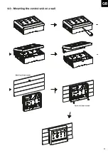
Page 90: ...6 D 6 0 Wandmontage Steuerger t 2 St ck Schrauben 4 x 25 mm 1 St ck Schraube 4 x 25 mm...
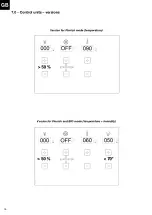
Page 91: ...7 D 7 0 Steuerger te Ausf hrungen 50 50 70...
Page 98: ...14 D Einstellung Beleuchtung 50 70 50 70 050...
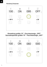
Page 100: ...16 D Einstellung Temperatur 50 70 50 70...
Page 101: ...17 D Einstellung Feuchte 50 70 50 70...
Page 102: ...18 D 50 70...
Page 117: ...33 GB Adjusting the lighting 50 70 50 70 050...
Page 136: ...52 50 70 50 70 050 F R glage de l clairage...
Page 155: ...71 50 70 50 70 050 I Regolazione dell illuminazione...
Page 159: ...75 50 70 I Se una funzione attiva il LED illuminato Il LED spento se una funzione non attiva...
Page 174: ...90 50 70 50 70 050 Regulaci n de la iluminaci n E...
Page 193: ...109 D 50 70 50 70 050 NL Instelling verlichting...
Page 212: ...128 50 70 50 70 050 CZ Nastaven osv tlen...
Page 221: ...137 D 13 1 St ckliste Sauna Control FIN Sauna Control FIN Artikelnummer 37 470 01 I Nr 18012...
Page 223: ...139 D 13 3 St ckliste Sauna Control BIO Sauna Control BIO Artikelnummer 37 470 11 I Nr 18012...
Page 232: ...148 CZ...
Page 238: ...154 D Stand 03 2019...


