background image

Allgemeines

5. 1  Gerätebeschreibung

Der ENDOFLATOR

®

 50 ist ein Insufflationsgerät 

zur universellen Anwendung bei laparoskopi

-

schen und thorakoskopischen Untersuchungen 

und Operationen sowie der Endoskopie des 

oberen und unteren Gastrointestinaltraktes 

(z. B. TEO

®

, Koloskopie). Des Weiteren ist der 

ENDOFLATOR

®

 50 für die Verdrängung der 

Umgebungsluft bei der offenen und endoskopisch 

assistierten Herzchirurgie sowie der endoskopischen 

Gefäßentnahme konzipiert. Neueste Technologien 

zur Druck- und Flow-Messung und -kontrolle 

ermöglichen unterschiedliche, auch auf spezifische 

Situationen zugeschnittene  Betriebsarten.
Die Abdeckung der verschiedenen 

Anwendungsbereiche wird durch die Modi 

»PÄDIATRIE« und »HIGH FLOW« erleichtert. 

 Einfache Handhabung und übersichtliche 

Kontrolleinrichtungen gewährleisten in Verbindung 

mit mehreren Si cher  heits schaltungen höchste 

Patientensicherheit.
Für besonders sensible Anwendungen bie

-

tet das Gerät den Modus »PÄDIATRIE« an, 

dessen Regelung sich durch einen nied

-

rigeren Insufflationsdruck sowie spezielle 

Sicherheitsgrenzen im Druck- (bis max. 15 mmHg) 

und Flussbereich (bis max. 15 l/min) auszeichnet. 
Dieser Modus beinhaltet auch eine engere 

Steuerung der Durchflussrate bei niedrigen 

Durchflüssen.
Um die bei komplizierten  laparoskopischen 

Operationen auftretenden starken 

Gasverluste schnell auszugleichen, wurde der 

ENDOFLATOR

®

 50 für eine hohe Flow-Leistung 

von bis zu 50 l/min ausgelegt.
Durch Verwendung eines Insufflationsschlauches 

mit integrierter Gasheizung kann das Risiko einer 

Hypothermie reduziert werden. 
Der ENDOFLATOR

®

 50 wird direkt über einen 

Farbbildschirm mit berührungsempfindlicher 

Oberfläche (Touchscreen) oder von einer externen 

Leitzentrale über die SCB-Schnittstelle bedient.
Die Bedienung präsentiert in übersichtlicher Weise 

jene Informationen, die im aktuellen Kontext 

4

Allgemeines

General information

5. 1  Description of the device

The ENDOFLATOR

®

 50 is an insufflation device 

for universal application in laparoscopic and 

thoracoscopic examinations and operations 

as well as endoscopy of the upper and lower 

gastrointestinal tract: (e.g., TEO

®

, colonoscopy). 

In addition, the ENDOFLATOR

®

 50 is designed to 

expulse ambient air in open and endoscopically 

assisted cardiac surgery as well as endoscopic 

vessel harvesting. The very latest technologies for 

pressure and flow measurement and control allow 

for various operating modes, including modes 

tailored to specific situations. 
The ‘PEDIATRICS’ and ‘HIGH FLOW’ modes 

enable various applications to be accommodated. 

Easy handling and clearly arranged controls 

together with several safety circuits ensure 

maximum patient safety.
For particularly sensitive applications, the 

device features a ‘PEDIATRICS’ mode which is 

characterized by low insufflation pressure as well 

as special safety limits in the pressure (up to max. 

15 mmHg) and flow ranges (up to max. 15 l/min). 
This mode also includes tighter control over the 

flow rate at low flows.
To quickly compensate for the considerable loss of 

gas occurring in complex laparoscopic operations, 

the ENDOFLATOR

®

 50 has been designed for a 

high flow rate of up to 50 l/min.
Use of an insufflation tube with integrated gas 

heater can reduce the risk of hypothermia.
The ENDOFLATOR

®

 50 is operated directly via a 

color screen with a touch-sensitive surface (touch 

screen) or by an external prime control unit via the 

SCB interface. 
The operation displays the information required in 

the specific context to enable a comprehensive 

assessment of the situation in a clear manner, and 

guides and aids the user with all device-related 

work. 

Generalidades

5. 1  Descripción del aparato

El ENDOFLATOR

®

 50 es un aparato de insuflación 

de aplicación universal en las exploraciones 

e intervenciones quirúrgicas laparoscópicas y 

toracoscópicas, así como en la endoscopia 

del tracto gastrointestinal superior e inferior 

(p. ej., TEO

®

, colonoscopia). Asimismo, el 

ENDOFLATOR

®

 50 ha sido diseñado para suprimir 

el aire ambiente en el caso de cirugía cardíaca 

abierta y asistida endoscópicamente, así como 

para la extracción endoscópica de vasos.

 La 

tecnología más moderna para la medición y 

el control de la presión y el flujo proporciona 

diferentes modos de servicio, incluyendo modos 

adecuados para situaciones específicas. 

La selección de los modos “

PEDIATRÍA

” y “HIGH 

FLOW” facilita su aplicación en los diferentes ámbi

-

tos de aplicación. Su sencillo manejo y sus instala

-

ciones de control claramente dispuestas, en com

-

binación con varios circuitos de seguridad positiva 

garantizan la mayor seguridad para el paciente.

Para las aplicaciones particularmente delicadas, 

el aparato ofrece el modo “

PEDIATRÍA

”, el cual se 

caracteriza por regularse con una presión de insu-

flación más baja y con unos límites de seguridad 

específicos en los rangos de presión (15 mmHg 

como máximo) y de flujo (15 l/min como máximo). 
Este modo contiene también un control más 

estricto de la tasa de flujo en caso de flujos bajos.
A fin de compensar rápidamente las fuertes 

pérdidas de gas que suelen producirse durante 

intervenciones laparoscópicas complicadas, el 

ENDOFLATOR

®

 50 ha sido previsto para propor-

cionar una elevada potencia de flujo que alcanza 

hasta 50 l/min.

Utilizando un tubo flexible de insuflación con un 

calefactor de gas integrado se puede reducir el 

riesgo de una hipotermia.

El ENDOFLATOR

®

 50 se maneja directamente a 

través de una pantalla de color con superficie sen-

sible al tacto (touch screen) o desde una central 

externa de mando a través de la interfaz SCB. 
El manejo presenta de forma sinóptica aquellas 

informaciones que son necesarias en el contexto 

actual para efectuar una evaluación exhaustiva de 

Generalidades

General information

Summary of Contents for ENDOFLATOR 50

Page 1: ...GEBRAUCHSANWEISUNG UI 500 ENDOFLATOR 50 INSTRUCTION MANUAL UI 500 ENDOFLATOR 50 MANUAL DE INSTRUCCIONES UI 500 ENDOFLATOR 50 ...

Page 2: ......

Page 3: ...years of experience and careful manufacturing You and your organization have decided in favor of a modern high quality product from KARL STORZ This instruction manual is intended to serve as an aid in the proper installation connection and operation of the ENDOFLATOR 50 All of the necessary details and actions are clearly explained Please read these instructions carefully Keep this manual in a con...

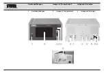
Page 4: ...2 Geräteabbildungen 1 6 8 9 0 q 2 3 4 5 7 w e IV Imágenes del equipo Images of the equipment Geräteabbildungen 2 Images of the equipment 2 Imágenes del equipo ...

Page 5: ...r switch O off 2 Touch screen 3 Insufflation connection to patient 4 Connection for patient tube heating 5 Room temperature sensor 6 Gas connection American connection 7 SCB connectors 8 Service interface concealed 9 Ethernet interface concealed 0 Potential equalization connector q Power cord socket w Line fuse holder e Holder for CO2 bottle optional cat no UI 005 3 Elementos de control indicadore...

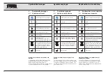
Page 6: ...S Este aparato está identificado con forme a la directiva europea referi da a aparatos eléctricos y electró nicos viejos Waste Electrical and Electronic Equipment o WEEE Fabricante Symbole auf Label und Verpackung des Gerätes Die Bedeutung der auf Label oder Verpackung aufgedruckten Symbole können Sie dem Beipackzettel Verpackungssymbole Mat Nr 96216316 DF entnehmen Diesen können Sie unter www kar...

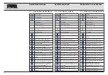
Page 7: ...trada correcta Acometida presión de entrada demasiado baja o demasiado alta Botella de gas presión de entrada por encima de 30 bares Botella de gas presión de entrada entre 20 y 30 bares Botella de gas presión de entrada entre 10 y 20 bares Botella de gas presión de entrada por debajo de 10 bares Botella de gas presión de entrada a 1 bar Botella de gas presión de entrada demasiado alta Indicador d...

Page 8: ...d Verwendbar bis Chargencode Manufacturer Catalogue number Do not reuse Do not resterilize CE mark Do not use if package is damaged Consult instructions for use Rx ONLY Federal USA law restricts this device to sale by or on the order of a physician Keep dry Keep away from sunlight Sterilized using ethylene oxide Use by date Batch code Fabricante Número de catálogo No reutilizar No esterilizar Símb...

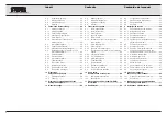
Page 9: ...f physician and assistants 18 6 5 Intended conditions of use 19 6 5 1 Use 19 6 5 2 Other intended conditions 19 6 5 3 User position 19 6 6 Safety precautions at the installation site 20 6 7 Safety precautions when operating the device 20 6 8 Safety features 21 6 8 1 Self test 21 6 8 2 Monitoring during operation 21 7 Installation and operating instructions 23 7 1 Unpacking the equipment 23 7 2 Bas...

Page 10: ...2 insufflation 37 7 4 9 Decommissioning 37 7 5 Menu explanations 38 7 5 1 Procedure list 38 7 6 Settings 41 7 6 1 Device settings 41 7 6 2 Service 41 7 6 3 System Log 41 7 6 4 Administration 42 7 6 5 Device information 43 8 Maintenance 44 8 1 Fuse replacement 44 8 2 Reprocessing 45 8 2 1 Reprocessing of the ENDOFLATOR 50 46 8 2 2 Reprocessing of heatable non heatable insufflation tubing set with g...

Page 11: ...0 9 2 2 Acoustic information signal 60 9 3 Test conditions for alarm and information signals 62 9 3 1 Overpressure alarm 62 9 3 2 CO2 empty alarm 62 9 3 3 Information signals 62 9 4 Troubleshooting 63 9 5 Technical data 66 9 5 1 Standard compliance 67 9 5 2 Directive compliance 67 9 6 Technical documentation 68 10 Spare parts recommended accessories 69 10 1 Spare parts accessories 69 10 2 Accessor...

Page 12: ...rized by low insufflation pressure as well as special safety limits in the pressure up to max 15 mmHg and flow ranges up to max 15 l min This mode also includes tighter control over the flow rate at low flows To quickly compensate for the considerable loss of gas occurring in complex laparoscopic operations the ENDOFLATOR 50 has been designed for a high flow rate of up to 50 l min Use of an insuff...

Page 13: ...nt of gas used during the current intervention are displayed simultaneously during operation The user is able to save his standard settings as a procedure max 30 5 1 1 Property rights This product is protected in the USA by at least one of the following US Patent s 5 788 688 6 397 286 6 484 221 6 824 539 la situación y guía y apoya al usuario en sus acti vidades relacionadas con el aparato De este...

Page 14: ...hey are accompanied by a pictogram 3 3 WARNING A Warning indicates that the personal safety of the patient or physician may be endangered Failure to observe a Warning could result in injury to the patient or physician 2 2 CAUTION A Caution indicates that particular service procedures or precautions must be followed to avoid possible damage to the device 1 1 NOTE A Note provides special information...

Page 15: ...6 of the 3rd edition of the IEC 60601 1 3 3 WARNING Grounding reliability can only be achieved when the device is connected to a Hospital only or Hospital Grade outlet Check the plugs and cables regularly and do not use if damaged 3 3 WARNING To avoid the risk of an electric shock this device may only be connected to a power supply network with a protective conductor 3 3 WARNING Test this equipmen...

Page 16: ... continuous operation a self test must be performed Take note of the warnings to ensure that the device is fully functional 3 3 WARNING The device must not be used if either the touch screen or display is defective 3 3 WARNING If the touch screen does not react when pressed you must turn the device off 3 3 WARNING Do not press several points on the touch screen simultaneously 3 3 WARNING Only ster...

Page 17: ...ways keep a spare device to hand in case the first device should fail 3 3 WARNING For safety reasons do not simultaneously touch the device output sockets and the patient 3 3 WARNING The device may only be operated with patient tube heating heatable insufflation tube sets supplied by KARL STORZ The connection socket 4 on the front panel is intended solely for connection of the patient tube heating...

Page 18: ...d Replace the CO2 filter after every use 3 3 WARNING Ensure that liquid cannot flow back into the device Position the device higher than the patient and use a hydrophobic filter between the insufflation connection and insufflation tube 3 3 WARNING Check the packaging of the tube set for damage If the packaging is damaged the sterility of the tube set may be impaired and the tube set must not be us...

Page 19: ... in the individual instructions for use Before using the device on the patient for the first time it is imperative that you be acquainted with how the device operates and is controlled 6 2 Intended use CO2 insufflators and their accessories are used to create and maintain a cavity during diagnostic or therapeutic endoscopic interventions as well as to expulse ambient air during open endoscopically...

Page 20: ...RNING Additional devices which are connected to electrical medical devices must comply with the relevant IEC or ISO standards e g IEC 60950 for data processing devices Furthermore all configurations must comply with the requirements for medical electrical systems see IEC 60601 1 1 or para 16 of the 3rd edition of the IEC 60601 1 Anybody connecting additional devices to electrical medical devices i...

Page 21: ...low and or excessive pressure The abdomen can be adequately distended by pressure in the range of 15 20 mmHg It is seldom necessary to use an abdominal pressure greater than 20 mmHg Little intravasation should occur at these levels Pressures over 20 mmHg are virtually never needed and will increase the amount and rapidity of intravasation Adequate respirations help avoid problems related to CO2 Me...

Page 22: ...orption is increased for patients with sickle cell anemia or pulmonary insufficiency Dehydration For longer operations with high gas levels insufflation can lead to a drying out of the tissues or cause tissue damage Unnecessary leaks must be avoided for this reason The decisive factor for the incidence of these complications is the length of the pneumoperitoneum the level of the intraabdominal pre...

Page 23: ... pneumoscrotum Increased airway pressure PEDIATRICS MODE When laparoscopic procedures are performed on children the increased intraabdominal pressure also increases the risk for higher airway pressures Always strictly monitor respiration and airway function when performing laparoscopic procedures on children younger than 12 years of age Compression of the vena cava PEDIATRICS MODE When insufflatin...

Page 24: ...orption Endoscopic Vessel Harvesting Due to the special surgical procedures start of the heart bypass operation and the endoscopic removal of the vessel special care has to be taken as CO2 is always absorbed through the tissue of the patient during insufflation intravasation This means the body absorbs part of the CO2 gas used for insufflation CO2 concentrations in the blood or respiratory system ...

Page 25: ...r reactions of the patient Long surgeries and large leaks increase the risk of dehydration especially at the insertion points of the trocars or when changing instruments Embolism Endoscopic Vessel Harvesting Improper placement of the insufflation instrument could cause insufflation of gas into a vessel resulting in air or CO2 embolisms To reduce the risk of air or CO2 embolism perform initial insu...

Page 26: ...ed medical staff Adequate powers of comprehension to rationally assess the situation in hand Familiarity with the use of technical apparatus Suitable command of one of the languages used by the device and in the instruction manual Must have been trained thoroughly at least once in the use of the device No physical impairments which limit or prevent perception of acoustic or visual alarm signals 6 ...

Page 27: ...on free surface Mobility can be moved if positioned on a cart Combination can be used on the patient at the same time as other equipment required for the operations Control can be controlled via the KARL STORZ SCB The device is placed outside the sterile area 6 5 3 User position To operate the device the user should always be standing in front of the device within a cone of vision with an opening ...

Page 28: ...oxygenated environments This also applies for easily combustible and explosive chemicals e g skin disinfectants and fast acting surface disinfectants The device is equipped with a connector for attaching a ground line It should be connected up in accordance with the applicable national regulations 6 7 Safety precautions when operating the device It is the user s responsibility to make sure the equ...

Page 29: ...setpoint value by a limit dependent on the setpoint value for more than 3 seconds an acoustic signal sounds see chapter 9 2 2 and the gas supply is stopped After a time period of 5 seconds the overpressure is actively reduced via a blow off valve or shown by a symbol that it is deactivated Mode specific pressure monitoring Monitoring of gas supply If the system recognizes a lack of CO2 gas when sw...

Page 30: ...ensures that the gas temperature does not exceed 41 C Passive safety measures The pressure and flow measurement systems have a redundant stand by Both pressure control stages and the flow measurement are equipped with safety pressure release valves The function of the mechanical high pressure regulator is monitored 1 1 NOTE If the monitoring system recognizes an error which renders safe functionin...

Page 31: ... UI 500 1 Power cord 400 A 3 Heatable insufflation tubing sets with gas filter single use sterile 1x 031210 03 package of 3 1 Universal wrench 20 4000 30 1 SCB connecting cable 20 0901 70 length 100 cm 1 Instruction manual 96116045D 1 CO2 supply tube customized Montaje e instrucciones operativas Installation and operating instructions 7 Montaje e instrucciones operativas 7 1 Desembalaje Extraiga c...

Page 32: ...rformed by qualified personnel 7 3 2 Connecting the power cord 3 3 WARNING The device may only be operated at the voltage stated on the rating plate 4 Push the power cord into the power socket as far as it will go Fig 3 3 3 WARNING Only connect disconnect the power plug to from the power supply outside of areas subject to explosion hazards 3 3 WARNING The instrument may only be operated with the p...

Page 33: ...CB connector possesses a protection device Therefore to unplug the SCB cable pull out the connector do not pull directly on the cable Connect the SCB cable to an equivalent SCB socket on the back of the device Fig 4 Connect the other end of the cable to the KARL STORZ SCB KARL STORZ Communication Bus control device or other SCB devices see KARL STORZ SCB control NEO System Instruction Manual 7 3 3...

Page 34: ...e y fíjela bloqueando el cierre en forma de estribo 3 3 CUIDADO Este equipo debe utilizarse ex clusivamente con gas CO2 para uso médico 7 3 5 Connecting the CO2 bottle Connect the gas outlet of the CO2 bottle to the device s gas connection using the high pressure tube supplied Fig 6 7 3 3 WARNING CO2 bottles connected up to the device must be secured to prevent them from falling over 3 3 WARNING F...

Page 35: ... 7 3 9 Connecting to the central gas supply Connect the low pressure tube e g UI 001 see the section Accessories to the device s gas connection and connect the other end directly to the wall outlet of the central gas supply 3 3 7 bar Fig 12 7 4 Commissioning 1 1 NOTE The gas supply must be connected when the device is switched on otherwise an error message is emitted 7 4 1 Commissioning for the fi...

Page 36: ...mode the acoustic availability signal sounded See section 9 1 5 Montaje e instrucciones operativas Installation and operating instructions 1 Accione el interruptor de red Después de la conexión en primer lugar aparece una pantalla con el logotipo de KARL STORZ fig 13 A continuación aparece una pantalla blanca Durante este tiempo el aparato lleva a cabo un test automático En caso de finalizar el te...

Page 37: ...in the chapter Technical description Troubleshooting In normal cases The switch on message is followed by the selected screen PEDIATRICS HIGH FLOW or Procedure list Fig 18 20 1 1 NOTE On the work screens PEDIATRICS Fig 18 and HIGH FLOW Fig 19 insufflation can be started directly device settings can be changed and the procedure information can be called up On the Procedure list screen Fig 20 a save...

Page 38: ...ettings Fig 22 Language Source of gas supply Volume Overpressure valve activation Modificación del idioma y otros preajustes 1 1 NOTA El idioma de visualización preajusta do es Inglés Aparece la pantalla Settings Ajustes fig 21 4 Pulse ahora el botón Device Settings Ajustes del aparato Acto seguido aparece la pantalla Device Settings Ajustes del aparato la cual muestra la lista de selección de aju...

Page 39: ...justes de volumen el volumen que desee para las advertencias y el sonido de las teclas fig 25 Margen de ajuste Advertencias 1 4 Margen de ajuste Sonido de las teclas 0 4 Confirme la opción seleccionada pulsando t o bien cancele los cambios pulsando r 8 Select the desired setting for the overpressure valve under Overpressure valve activation On or Off Fig 26 Confirm the selection with t or reject t...

Page 40: ... PEDIATRICS mode Setting Setting after restart Pressure 1 12 mmHg 1 12 mmHg 13 15 mmHg 12 mmHg Flow 0 1 1 l min 0 1 1 l min 1 1 l min 1 l min 1 1 NOTE On the work screens PEDIAT RICS Fig 28 and HIGH FLOW Fig 29 insufflation can be started directly device settings can be changed and the procedure information can be called up On the Pro cedure list screen Fig 30 if necessary a saved procedure can be...

Page 41: ...be Connecting the heatable patient tube Connect the connecting cable of the heatable patient tube to the socket 4 on the ENDOFLATOR 50 Fig 32 The heating function is activated by plugging in the connecting cable 1 1 NOTE The patient tube heating symbol 7 is displayed in the Working screen Fig 33 The CO2 gas flowing through is heated to a temperature of approx 37 C The unit adapts to various flow r...

Page 42: ...value and which after a few seconds is released via the blow off valve 6 Observe the instrument s conduct over a 30 second period 1 1 NOTE The flow display may only show values greater than zero for short periods If the set pressure is only reached slowly even when the instrument s stopcock is closed or if you note stationary flow rates of 0 2 l min or more there is a leak in the system filter pat...

Page 43: ...ure list screen appears Fig 36 2 Select the desired procedure by tapping e g 3 By tapping on button 4 the device jumps back to the working screen without any changes being made The Working screen appears Fig 34 or 35 The ENDOFLATOR 50 is equipped with two different insufflation modes HIGH FLOW man symbol PEDIATRICS baby symbol 1 1 NOTE To compensate for the considerable loss of gas occurring in co...

Page 44: ... 4 6 Recommended settings for pediatric subcategories Group Weight Flow range Children younger than 1 year Approx 1 9 kg 0 1 0 5 l min Children between 1 and 3 years Approx 10 15 kg 0 5 1 0 l min Children between 3 and 4 years Approx 16 19 kg 1 0 2 0 l min Children between 4 and 14 years 20 kg 2 0 l min All Children 25 kg 14 0 l min 7 4 7 Recommended settings for endoscopic vessel harvesting Group...

Page 45: ...he insufflation tube must be removed in this case 1 1 NOTE In the case of disposable tubing sets cut the tube off behind the LUER lock Displays The insufflation pressure flow and volume of the gas used are continuously displayed in the Working screen Fig 37 If the patient pressure rises above the preselected value an audible warning signal will be sounded The pressure is reduced via the overpressu...

Page 46: ...aved as a new procedure 1 1 NOTE By tapping on the button 4 the device jumps back to the Working screen without any changes being made Creating a new procedure 1 Tap on button 2 see Figs 39 resp 40 to call up the Procedure list screen if necessary also see Section 7 4 2 The Procedure list screen shows any saved procedures Fig 41 2 Tap on button 3 Create a new procedure Fig 41 1 1 NOTE If 30 proced...

Page 47: ... status of the buttons z and u By pressing the arrow buttons i or o the cursor moves one character to the left or right Use the button p to delete the character to the left of the cursor 5 Tap on the button t to confirm the input When a new procedure is created the device returns to the Procedure list screen see Fig 44 Editing an existing procedure 1 Tap on button 8 in the Procedure list screen se...

Page 48: ...ist screen appears again see Fig 48 Deleting an existing procedure 1 Call up the Edit procedure list screen in the same way as described for editing an existing procedure see Fig 45 page 35 2 Select the procedure using the buttons 6 if necessary 3 Tap the trash can button next to the procedure to be deleted The Delete procedure screen appears see Fig 49 4 Confirm the deletion of the procedure by t...

Page 49: ...g contains the saved information and alarms Fig 53 Each entry occupies one row and consists of a sequential number date time and alarm information ID The most recent entry is allocated the number 000 In case of voltage drops or shut downs the system log is saved and contains entries concerning start up and shut down times 7 6 Ajustes Ajustes del aparato Device Settings Servicio Técnico Service Reg...

Page 50: ...e de fecha y hora Date and Time Modificar la contraseña de Administración Change administration password 1 1 NOTA La pantalla Administration Adminis tración está protegida mediante contraseña La contraseña por defecto es 2132 Es responsabilidad del usuario cambiar esta contraseña Exportar archivo de registro Export system log Con fines de servicio técnico es posible exportar datos a una memoria US...

Page 51: ...da pulsando t o bien cancele los cambios pulsando r 7 6 5 Información acerca del aparato La información acerca del aparato Device infor mation indica los siguientes elementos fig 60 el número de serie del aparato las horas de servicio las versiones del software los datos de la licencia del software t r 59 59 60 Einheiten Druck Unit pressure Unter Einheiten Druck die gewünschte Einheit mmHg oder hP...

Page 52: ...der w using a screwdriver or another suitable tool Fig 62 3 3 WARNING Only use fuses of the correct rating 3 Insert new fuses Fig 63 100 240 V Line fuse 2 x T2 5 AH 250 V 4 Now put the line fuse holder w on again 5 Restore the power supply 6 Switch the device on Fig 64 and ensure that the start screen appears 8 Mantenimiento 8 1 Cambio de fusibles 1 Desconecte el aparato y desenchúfelo de la red f...

Page 53: ...ble insufflation tube for visible contamination Visible contamination is an indication that reprocessing has not been carried out or has been carried out incorrectly Reprocess the reusable insufflation tube before initial use and before and after every subsequent use using validated procedures 3 3 WARNING When carrying out any work on contaminated medical devices the guidelines of the Employer s L...

Page 54: ...z com 8 2 1 Reprocessing of the ENDOFLATOR 50 3 3 WARNING Always disconnect the device from the mains before cleaning 3 3 WARNING Liquid must not be allowed to enter the housing under any circumstances Manual wipe down disinfection of device and supply tube Wipe clean the exterior surfaces of the medical device with a disposable cloth moistened with disinfectant or a ready to use soaked disinfecta...

Page 55: ...ssories required for carrying out reprocessing Brushes 27652 27650 A 27650 B 8 2 3 2 Preparation for cleaning and disinfection Heavy soiling corrosive solutions and pharmaceuticals must be removed from the medical device immediately after use To this end preclean the medical device by wiping down and rinsing for example As a general rule KARL STORZ recommends manual precleaning under cold running ...

Page 56: ... manual Sumerja completamente el producto médico en una solución de limpieza Llene los lúmenes para asegurar una humectación sin burbujas Una vez concluido el tiempo de aplicación efectúe la limpieza mecánica con cepillos o una esponja Por último enjuague con agua fría para asegurar la neutralización 8 2 3 5 Desinfección manual Sumerja completamente el producto médico en una solución desinfectante...

Page 57: ... 1 1 NOTA Si es necesario efectúe un secado manual posterior del instrumento Conexión A fin de garantizar una limpieza y desinfección mecánicas efectivas es necesario conectar el ins trumento al aparato de limpieza y desinfección y así asegurar un enjuage completo 8 2 3 7 Montaje verificación y conservación 3 3 CUIDADO Es estrictamente necesario llevar a cabo un control visual y de funcionamiento ...

Page 58: ...tilizable de la siguiente forma Coloque una jeringa en un extremo del tubo flexible y doble el otro extremo Deposite el tubo flexible de insuflación en agua completamente desalinizada o en agua microbiológicamente pura esterilizada Introduzca aire en el tubo flexible de insuflación utilizando la jeringa Si durante este proceso aparecen burbujas de aire no debe volver a utilizar el tubo flexible de...

Page 59: ...cto médico han sido validados y autorizados por KARL STORZ Esterilización por vapor por el procedimiento de prevacío fraccionado Para una esterilización del producto médico estando este montado se recomienda utilizar un procedimiento de prevacío fraccionado DIN EN ISO 17665 1 a 132 C 137 C durante un tiempo mínimo de aplicación de 3 hasta un máximo de 18 minutos Este procedimiento solo es adecuado...

Page 60: ...z al año verificaciones de seguridad verificaciones periódicas según la norma CEI 62353 en este aparato y protocolizar dichos controles Inspección visual 1 Compruebe que el aparato y los accesorios no presentan deterioros mecánicos que pue dan menoscabar su buen funcionamiento 2 Compruebe la legibilidad de los rótulos relevantes para la seguridad Mediciones eléctricas Control de los fusibles del a...

Page 61: ... del alcance y ejecución de las verifi caciones de seguridad verificaciones perió dicas en la edición actual del correspondien te Manual de servicio 8 4 Reparaciones 3 3 CUIDADO Los equipos averia dos sólo deberán ser reparados por KARL STORZ o por personas autorizadas por KARL STORZ y utilizando única mente piezas de repuesto originales de KARL STORZ 8 5 Gestión de desecho Este aparato está ident...

Page 62: ...f Gewerbepark 83 78579 Neuhausen Servicio de atención telefónica 49 7461 708 980 Correo electrónico technicalsupport karlstorz com 8 7 Observaciones importantes Con el fin de prevenir infecciones rechazamos estrictamente la recepción de envíos de productos sanitarios contaminados Los productos sanitarios han de ser descontaminados directamente in situ con el fin de evitar infecciones aerógenas o p...

Page 63: ...nd the device has been used in accordance with its operating instructions at all times 8 9 Warranty The guarantees provided can be found in the Standard Conditions of Business of KARL STORZ The medical device must always be sent to your local subsidiary see Subsidiaries section even during the warranty period Opening the equipment or performance of any repairs or modifications to the equipment by ...

Page 64: ...vated 0 5 s after the cavity pressure measurement PEDIATRICS mode The overpressure alarm is triggered if as a product of the setpoint the mea sured cavity pressure is 3 to 4 mmHg above the set setpoint value or if the cavity pressure is the same or larger than 16 mmHg HIGH FLOW mode The overpressure alarm is triggered if as a product of the setpoint the mea sured cavity pressure is 4 to 5 mmHg abo...

Page 65: ...ring to one decimal place as the threshold is calculated depending on the setpoint value Pressure set point value Overpressure alarm threshold PEDIA TRICS mode 1 mmHg 15 mmHg 2 6 mmHg 4 mmHg or pres sure 16 mmHg HIGH FLOW mode 1 mmHg 30 mmHg 3 6 mmHg 5 mmHg or pres sure 31 mmHg CO2 empty alarm Low priority CO2 empty alarm 373 CO2 empty see 9 1 indicates that the gas supply failed dur ing the appli...

Page 66: ...r an acoustic signal is met at least one complete sequence is played The volume of the audio signals can be adapted in Settings Furthermore the alarm audio signals can be deactivated for 30 s by tapping on the Bell alarm audio paused The bell turns yellow during this time Fig 68 At the maximum setting the alarm volume is 74 dBA and at the minimum setting 49 dBA Medium priority alarm signal 170 ms ...

Page 67: ...tioning of the alarm system The functioning of the alarm system is verified with the sounding of the availability signal after the mode has been selected The individual alarm conditions can be tested as described in section 9 3 9 2 Information signals The information signals are self explanatory mes sages which explain the device behavior support users with the individual operating functions and t...

Page 68: ...alarm signal with a higher priority or a low prior ity information signal is suppressed for as long as there is a signal with a higher priority If numerous signal conditions with the same priority occur the most recently detected condition overwrites earlier ones in the title line of the display 9 2 1 Visual signals The information signals are also shown in the title line Information signals are d...

Page 69: ...layed just once Availability signal On completion of the successful self test after switching on the device an availability signal with the following characteristics sounds Amplitude Time c 100 ms e g h The pitch is modulated by 2 Hz with a modulation frequency of 1 5 Hz Five different harmonics are generated Key click Tapping on a key on the touch screen is indicated by a short beep The volume of...

Page 70: ...erpressure condition continues to apply when the system is leakproof 9 3 2 CO2 empty alarm 1 Before turning on the device open the gas supply briefly and then close again 2 Turn on the device and after a successful switch on test start insufflation with a flow limit of 1 Once the input pressure has been reduced a CO2 empty alarm sounds 9 3 3 Information signals 1 Proceed as with CO2 empty alarm an...

Page 71: ...nit off and back on If the warning message still appears after restarting contact Service Prior to this open the System Log under Settings and note the ID Word1 Word2 and information text of the last 5 entries Description of error No gas flow Measure Observe the warnings device temperature exceeded temperature of high pressure regulator too low gas supply not sufficient If the warning message stil...

Page 72: ...a high level of instrument resistance and simultaneous gas outflow Depending on the instrument and leak conditions the current values for pressure and flow are below the setpoint values 3 a Check the connections of the accessories and the leakproofness of the trocar If the test for proper functioning is passed the likelihood of a loose connection is very high b Change the tube tube set and perform...

Page 73: ...heating is defective Action Replace the heatable patient tube and put the patient heating into operation by switching the device off and on again Error description After plugging in a heatable patient tube the patient heating symbol lights up white and then changes its color from white to red and the message Defective heated tube please replace is displayed Possible causes The patient heating is d...

Page 74: ...lationsdruck Insufflation pressure Presión de insuflación max máx 30 mmHg Betriebsart HIGH FLOW HIGH FLOW mode Modo de servicio HIGH FLOW Intrakavitärer Druck Intracavitary pressure Presión intracavitaria 1 30 mmHg Auflösung resolution resolución 1 mmHg Flow Flow Flujo 1 50 l min Auflösung resolution resolución 1 l min Insufflationsdruck Insufflation pressure Presión de insuflación max máx 50 mmHg...

Page 75: ...rt type CF 4 Type of IP protection IP21 According to IEC 60601 1 2 FCC B Observe the information on electromagnetic compatibility in chapter 11 pages 71 87 9 5 2 Directive compliance for UI 500 According to the Medical Device Directive MDD This medical product belongs to Class IIb This medical product bears the CE mark in accordance with the Medical Device Directive MDD 93 42 EEC 1 1 NOTE The code...

Page 76: ...y the manufacturer Supply of such technical documentation relating to the device shall not be construed as constituting manufacturer s authorization of user s personnel regardless of their level of technical training to open or repair the device Explicitly exempted herefrom are those maintenance and repair operations described in this manual 1 1 NOTE We reserve the right to make engineering modifi...

Page 77: ...nector PIN Index connector length 55 cm 20 4000 22 Same length 102 cm 20 4000 28 High pressure tube American connector ISO connector length 102 cm 20 4002 22 CO2 bottle 1 l empty with German connector 26 4000 90 CO2 bottle 1 l empty with PIN Index connector 26 4000 91 Low pressure tube for the central CO2 gas supply length 150 cm UI 001 Same length 300 cm UI 002 Same length 600 cm UI 003 HD Inline...

Page 78: ...ith spring loaded blunt stylet LUER lock length 10 cm 26120 J Same length 12 cm 26120 JL Same length 7 cm 26120 JK Same length 15 cm for creating pneumo peritonea by means of DOUGLAS puncture with adipose patients 26120 JF Bottle holder folding holder for KARL STORZ CO2 gas bottles 1000 ml UI 005 Leakage tester 13242 XL Artículo N º de pedido Tubo flexible de insuflación esterilizable 2 5 m de lon...

Page 79: ... the equipment and systems which generate or use RF energy only for their internal functioning 1 1 NOTE The tables and guidelines that are included in this section provide information to the customer or user that is essential in determining the suitability of the device or system for the electromagnetic environment of use and in managing the electromagnetic environment of use to permit the device ...

Page 80: ...of portable and mobile RF equipment may have an impact on this or other pieces of medical equipment 3 3 WARNING The use of accessories transducers and cables other than those specified in the KARL STORZ instruction manual may result in increased emissions or decreased immunity of the device The accessories transducers and cables listed below have been shown to comply with the requirements of IEC 6...

Page 81: ...r den Gebrauch in allen Einrichtungen einschließlich Wohnbereichen und solchen bestimmt die unmittelbar an ein öffentliches Versorgungsnetz angeschlossen sind das auch Gebäude versorgt die für Wohnzwecke genutzt werden Umgebung in professionellen Einrichtungen des Gesundheitswesens Aussendung von Oberschwin gungen nach IEC 61000 3 2 Klasse A Aussendungen von Spannungs schwankungen Flicker nach IEC...

Page 82: ...ER HÄUSLICHEN GESUNDHEITSFÜRSORGE ENTLADUNG STATISCHER ELEKTRIZITÄT IEC 61000 4 2 8 kV Kontakt 2 kV 4 kV 8 kV 15 kV Luft Hochfrequente elektromagnetische Felder IEC 61000 4 3 3 V m 80 MHz bis 2 7 GHz 80 AM bei 1 kHz Nicht zutreffend da nur für professionelle Einrichtungen des Gesundheitswesens freigegeben Hochfrequente elektromagnetische Felder in unmittelbarer Nachbarschaft von drahtlosen Kommuni...

Page 83: ...00 4 4 2 kV 100 kHz Wiederholfrequenz Stoßspannungen Leitung gegen Leitung IEC 61000 4 5 0 5 kV 1 kV Stoßspannungen Leitung gegen Erde IEC 61000 4 5 0 5 kV 1 kV 2 kV Leitungsgeführte Störgrößen induziert durch hochfrequente Felder IEC 61000 4 6 3 V 0 15 MHz bis 80 MHz 6 V in ISM Frequenzbändern zwischen 0 15 MHz und 80 MHz 80 AM bei 1 kHz Nicht zutreffend da nur für professionelle Einrichtungen de...

Page 84: ...eitungsgeführte Störgrößen induziert durch hochfrequente Felder IEC 61000 4 6 3 V 0 15 MHz bis 80 MHz 6 V in ISM Frequenzbändern zwischen 0 15 MHz und 80 MHz 80 AM bei 1 kHz Nicht zutreffend da nur für professionelle Einrichtungen des Gesundheitswesens freigegeben Tabelle 7 TORE von PATIENTEN Anschlüssen gemäß IEC 60601 1 2 Phänomen EMV Grundnorm STÖRFESTIGKEITS PRÜFPEGEL Professionelle Einrichtun...

Page 85: ...1 kHz Sinus 2 0 3 28 710 704 bis 787 LTE Band 13 17 Pulsmodulation 217 Hz 0 2 0 3 9 745 780 810 800 bis 960 GSM 800 900 TETRA 800 iDEN 820 CDMA 850 LTE Band 5 Pulsmodulation 18 Hz 2 0 3 28 870 930 1 720 1 700 bis 1 990 GSM 1800 CDMA 1900 GSM 1900 DECT LTE Band 1 3 4 25 UMTS Pulsmodulation 217 Hz 2 0 3 28 1 845 1 970 2 450 2 400 bis 2 570 Bluetooth WLAN 802 11 b g n RFID 2450 LTE Band 7 Pulsmodulat...

Page 86: ...magnetic environment guidance RF emissions CISPR 11 Group 1 The ENDOFLATOR 50 model UI 500 uses RF energy only for its internal function Therefore its RF emissions are very low and are not likely to cause interference in nearby electronic equipment RF emissions CISPR 11 Class B The ENDOFLATOR 50 model UI 500 is suitable for use in all establishments including domestic establishments and those dire...

Page 87: ...EVELS Professional healthcare facility environment HOME HEALTHCARE ENVIRONMENT ELECTROSTATIC DISCHARGE IEC 61000 4 2 8 kV contact 2 kV 4 kV 8 kV 15 kV air Radiated RF EM fields IEC 61000 4 3 3 V m 80 MHz 2 7 GHz 80 AM at 1 kHz Not applicable since released only for professional healthcare facility environment Proximity fields from RF wireless communications equipment IEC 61000 4 3 See table 9 RATE...

Page 88: ...rsts IEC 61000 4 4 2 kV 100 kHz repetition frequency Surges Line to line IEC 61000 4 5 0 5 kV 1 kV Surges Line to ground IEC 61000 4 5 0 5 kV 1 kV 2 kV Conducted disturbances induced by RF fields IEC 61000 4 6 3 V 0 15 MHz 80 MHz 6 V in ISM bands between 0 15 MHz and 80 MHz 80 AM at 1 kHz Not applicable since released only for professional healthcare facility environment Voltage dips IEC 61000 4 1...

Page 89: ...ound IEC 61000 4 5 2 kV Conducted disturbances induced by RF fields IEC 61000 4 6 3 V 0 15 MHz 80 MHz 6 V in ISM bands between 0 15 MHz and 80 MHz 80 AM at 1 kHz Not applicable since released only for professional healthcare facility environment Table 7 PATIENT coupling PORT according to IEC 60601 1 2 Phenomenon Basic EMC standard IMMUNITY TEST LEVELS Professional healthcare facility environment H...

Page 90: ...ine 2 0 3 28 710 704 787 LTE Band 13 17 Pulse modulation 217 Hz 0 2 0 3 9 745 780 810 800 960 GSM 800 900 TETRA 800 iDEN 820 CDMA 850 LTE Band 5 Pulse modulation 18 Hz 2 0 3 28 870 930 1 720 1 700 1 990 GSM 1800 CDMA 1900 GSM 1900 DECT LTE Band 1 3 4 25 UMTS Pulse modulation 217 Hz 2 0 3 28 1 845 1 970 2 450 2 400 2 570 Bluetooth WLAN 802 11 b g n RFID 2450 LTE Band 7 Pulse modulation 217 Hz 2 0 3...

Page 91: ...bajo El cliente o el usuario del ENDOFLATOR 50 modelo UI 500 debería asegurarse de que se use en dicho entorno Ensayo de emisiones Conformidad Entorno electromagnético Guía Emisiones de RF Norma CISPR 11 Grupo 1 El ENDOFLATOR 50 modelo UI 500 usa energía de RF sólo para su función interna Por ello sus emisiones de RF son muy bajas y no es probable que causen cualquier interferencia en los equipos ...

Page 92: ... EL ÁMBITO DE LA ASISTENCIA SANITARIA DOMÉSTICA DESCARGA ELECTROSTÁTICA CEI 61000 4 2 Contacto 8 kV Aire 2 kV 4 kV 8 kV 15 kV Campos electromagnéticos de alta frecuencia CEI 61000 4 3 3 V m 80 MHz hasta 2 7 GHz 80 AM a 1 kHz No aplicable ya que su uso solo está autorizado para establecimientos profesionales de atención sanitaria Campos electromagnéticos de alta frecuencia en las inmediaciones de a...

Page 93: ... 2 kV Frecuencia de repetición de 100 kHz Ondas de choque Línea a línea CEI 61000 4 5 0 5 kV 1 kV Ondas de choque Línea a tierra CEI 61000 4 5 0 5 kV 1 kV 2 kV Transitorios por conducción inducidos por campos de alta frecuencia CEI 61000 4 6 3 V 0 15 MHz hasta 80 MHz 6 V en bandas de frecuencia ISM entre 0 15 MHz y 80 MHz 80 AM a 1 kHz No aplicable ya que su uso solo está autorizado para estableci...

Page 94: ... inducidos por campos de alta frecuencia CEI 61000 4 6 3 V 0 15 MHz hasta 80 MHz 6 V en bandas de frecuencia ISM entre 0 15 MHz y 80 MHz 80 AM a 1 kHz No aplicable ya que su uso solo está autorizado para establecimientos profesionales de atención sanitaria Tabla 7 PUERTOS de conexiones a PACIENTES conforme a CEI 60601 1 2 Fenómeno Norma básica CEM NIVELES DE ENSAYO DE INMUNIDAD Establecimientos pr...

Page 95: ...ción 1 kHz seno 2 0 3 28 710 704 hasta 787 LTE Banda 13 17 Modulación por pulsos 217 Hz 0 2 0 3 9 745 780 810 800 hasta 960 GSM 800 900 TETRA 800 iDEN 820 CDMA 850 Banda LTE 5 Modulación por pulsos 18 Hz 2 0 3 28 870 930 1 720 1 700 hasta 1 990 GSM 1800 CDMA 1900 GSM 1900 DECT Banda LTE 1 3 4 25 UMTS Modulación por pulsos 217 Hz 2 0 3 28 1 845 1 970 2 450 2 400 hasta 2 570 Bluetooth WLAN 802 11 b ...

Page 96: ...Greece Phone 30 2310 304868 Fax 30 2310 304862 E Mail info gr karlstorz com Repair Service Subsidiary KARL STORZ Industrial Gedik Is Merkezi B Blok Kat 5 D 38 39 Bagdat Cad No 162 Maltepe Istanbul Turkey Phone 90 216 442 9500 Fax 90 216 442 9030 Sales for Industrial Endoscopy OOO KARL STORZ Endoskopy WOSTOK Derbenyevskaya nab 7 building 4 115114 Moscow Russia Phone 7 495 983 02 40 Fax 7 495 983 02...

Page 97: ......

Page 98: ...KARL STORZ SE Co KG Dr Karl Storz Straße 34 78532 Tuttlingen Postfach 230 78503 Tuttlingen Germany Telefon 49 0 7461 708 0 Telefax 49 0 7461 708 105 E Mail info karlstorz com Web www karlstorz com ...

Reviews: