background image

9

8


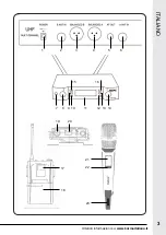
Before arranging any connection make sure that the power  


cord is unplugged from the mains.  All connections must be  


made with the device off. 

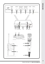
1.  Please be sure that the batteries in the transmitters are charged and if necessary 

replace them, by unscrewing the handle and paying attention to hold the upper 

grid, in order to avoid the capsule coverto open. Be careful to respect the indicated 

polarities.  If you use bodypack transmitters, plug the jack into the microphone’s 

socket (18).

2. 

Position correctly the receiving base, by keeping a distance of at least 1 mt from 

the floor or walls.  Connect it to mixers or amplifiers through the balanced  XRL  

sockets (3-4) or through the mixed socket with unbalanced Jack 6,3 mm (5) signal.  

The output signal is of microphone type.  Make sure that the antennas (which are 

to be connect to 2-6 sockets) are raised in vertical position. If you mean to mount 

the microphone in a 19” rack, you can do that thanks to the included brackets.

3. 

Connect the adaptor to the back socket (1) and then to the 230V domestic power 

source.  Warning: don’t connect the adaptor to the power socket before connecting 

the jack: this could cause a spark and damage the unit. 

4.  After turning on the other components of your audio system, press the ON/OFF 

key (7) on the base and then the ON / OFF key (20-23) on the transmitter. 

5. 

If you are using a bodypack transmitter, the back clip will allow you to fasten it to 

your belt for easy carriage. 

6. 

Adjust as you wish the receiver’s volume through the controls (8- 14) on the base.  

There are double controls to manage separately the two wireless microphones. The 

displays show information on the signals received by the 2 wireless microphones.  

In order to work correctly, transmitter and receiver must operate on the same frequency.    

You can set them manually,  by using the buttons (15-16) or (10-12) to choose the 

desired frequency. To send it to the transmitter, turn it on and place the infrared sensor 

(22) at some cm from the transmitting led (11) and then press once the key (9-13) to 

activate infrared transmission.  After a couple of seconds the process will be concluded 

and the microphone will indicate the same frequency as the receiving base. 

WARNING:

 the bodypack’s infrared sensor is behind the battery case’s cover (18).  

Open the cover to carry out the frequency matching procedure.

ENGLISH

Summary of Contents for SET 8102

Page 1: ...w w w k a r m a i t a l i a n a i t Manuale di istruzioni Instruction manual I E SET 8102 SET 8102LAV SET 8102PL Doppio radiomicrofono UHF Double UHF wireless microphones...

Page 2: ...la fiducia riposta nel nostro marchio Precauzioni ed avvertenze Conservare il manuale per future consultazioni e allegatelo se cedete l apparecchio ad altri Assicuratevi sempre di collegare l apparecc...

Page 3: ...Ulteriori informazioni su www karmaitaliana it 3 ITALIANO 1 2 3 4 5 6 7 11 8 14 10 12 13 9 15 16 20 18 23 19 17 22 21...

Page 4: ...ver collegato lo spinotto ci potrebbe provocare una scintilla e danneggiare l apparecchio 4 Dopo aver acceso gli altri componenti del vostro impianto audio premete il tasto di accensione 7 posto sulla...

Page 5: ...le Riferitevi alla figura sottostante per i dettagli delle informazioni Livello RF mostra la potenza del segnale portante Livello AF mostra la potenza del segnale vocale ricevuto Canale selezionato Fr...

Page 6: ...oid the risk of fire or short circuits never expose the fixture to rain or moisture Do not operate the product in an ambient temperature higher than 35 In the event of a serious operating problem stop...

Page 7: ...Ulteriori informazioni su www karmaitaliana it 7 ENGLISH 1 2 3 4 5 6 7 11 8 14 10 12 13 9 15 16 20 18 23 19 17 22 21...

Page 8: ...connect the adaptor to the power socket before connecting the jack this could cause a spark and damage the unit 4 After turning on the other components of your audio system press the ON OFF key 7 on...

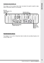
Page 9: ...nal s reception status Refer to the picture below for more details MICROPHONES DISPLAY The display 17 21 on the microphone shows besides the operating frequency the battery charge level ENGLISH RF Lev...

Page 10: ...t at the end of its service life the product must be collected separately from other wastes The user must therefore consign it complete with all its main components to a suitable separate collection c...

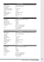
Page 11: ...40 a 790 Mhz Channels 16 Temperature da 10 a 50 Signal noise ratio 105 dB Spurious 80 dB Frequency Responce 60Hz 18KHz 3dB Operative range untill 50mt Dimensions 207 x 43 x 175 mm Weight 0 6 Kg MICROF...

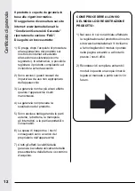
Page 12: ...esso 4 La garanzia non prevede la sostituzione del prodotto 5 Sono escluse dalla garanzia le parti esterne le batterie le manopole gli interruttori e le parti asportabili o consumabili 6 Le spese di t...

Page 13: ...NZIA GUARANTEE CERTIFICATE CERTIFICATO DI GARANZIA GUARANTEE CERTIFICATE MODULO DI REGISTRAZIONE REGISTRATION MODULE MODULO DI REGISTRAZIONE REGISTRATION MODULE COPIA DA INVIARE A COPIA DA CONSERVARE...

Page 14: ...CEIPT INVOICE NUMBER N SCONTRINO O FATTURA RECEIPT INVOICE NUMBER TIMBRO E FIRMA DEL RIVENDITORE DEALER S STAMP AND SIGNATURE TIMBRO E FIRMA DEL RIVENDITORE DEALER S STAMP AND SIGNATURE ACQUISTATO DA...

Page 15: ...responsabilit per l aquisizione della licenza per gli apparecchi radiomicrofonici e la licenziabilit dipende dalla classificazione e dall applicazione dell utente e della frequenza selezionata D Lgs...

Page 16: ...Via Gozzano 38 bis 21052 Busto Arsizio VA Italy Telefono 39 0331 628 244 Fax 39 0331 622 470 www karmaitaliana it made in China ver 17 1...

Reviews: