5.1JF PARTS INCLUDED
A. 5.1JF Aerating Fountain (Unit with cord or unit with Disconnect) (1)
A1. Cord in separate box (1) (depending on size of cord)
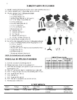
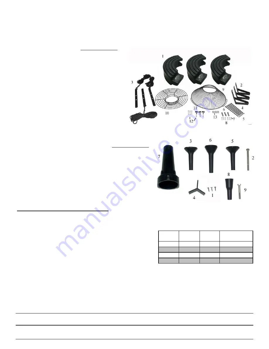
B. Float in separate box (1) (Diagram to Right)
1. 3 Float Sections (1)
2. Top Float Bracket (3)
3. Bottom Float Bracket w/ 50’ rope (3)
4. 9” x 3/8” Black Coated Bolt (6)
5. 3/8” Lock Nut (6)
6. Unit Mounting Bracket (3)
7. 1/4” x 3/4” Bolt (9)
8. 1/4” Lock Washer (12)
9. Bottom Screen (1)
10. Top Screen (1)
11. Top Screen Clip (3)
12. 1/4” Nut (6)
13. Bottom Screen Clip (3)
14. 1/4-20 x 3/4” Brass Screw (3)
C. C-95 Control Panel in separate box (1)
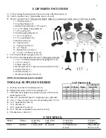
D. Set of Five Interchangeable Nozzles (5) (Diagram to Right)
1. #6 x 1/2” Phillip Pan Head Self Tapping Screw (3)
2. 3/8” x 4” Bolt (1)
3. Linden Nozzle (1)
4. Redwood Nozzle Y Insert (comes installed in #7)(1)
5. Juniper Nozzle (1)
6. Willow Nozzle (1)
7. Redwood & Spruce Nozzle (1)
8. Sequoia Nozzle
9. 3/8” x 2.5” Bolt (1)
NOTE: Extra hardware may be included.
TOOLS & SUPPLIES NEEDED
A. Anchors or stakes for installing unit (3)
B. Philips head screw driver for mounting C-95
C. 240V Electrical Supply near pond on a post with room for
mounting the C-95
D. Three 12” galvanized pipe for weighting ropes (optional)
G. #10 x 1” long or longer screw(s) for mounting the C-95 (4)
H. 7/16” Socket & Wrench (1)
* No plugs on all 5.1JF Cords. Unit must
I. 7/16” Wrench (1)
be hardwired into the C-95.
J. 9/16” Socket & Wrench (1)
K. 9/16” Wrench or adjustable crescent wrench (1)
L. Flat head screw driver (1)
UNIT SPECS.
Model
Voltage
Operating
Lock Rotor
Control Box
Fountain
Amps
Amps
Connection
Connection
5.1JF
208-240
20 @ 240V
97 @ 240V
C-95 Hardwired
Hardwire
at shore
in C-95
9
5.1JF Power Cords
Length Voltage Gauge
Cord Shipped
Seperately
100 240 12
Yes
150
240
10
Yes
200 240 10
Yes
250
240
8
Yes


