background image

This reaction is called blade thrust. As a result, 

the operator may lose control of the unit which 

may cause serious or fatal injury. Blade thrust 

is more likely to occur in areas where it is diffi 

cult to see the material to be cut.

Wear the harness as shown in the fi gure. The 

blade turns counter-clockwise, therefore, be 

advised to operate the unit from right to left for 

effi cient cutting. Keep onlookers out of working 

area at least 15 m.

Use in accordance with local laws and 

regulations.

○ 

○ 

NOTE

Pull emergency release fl ap in the event of 

emergency.

 (Fig. 25)

How to use the shoulder harness

Wear the shoulder harness on your shoulder 

as shown 

Fig. 23

 and hook it on the hanger of 

the machine. Adjust the length of the shoulder 

harness to the most comfortable position. 

(Fig. 

23)

To remove the machine from the shoulder 

harness, hold the main pipe of the machine fi rmly 

by one hand and then remove the hook (23) of 

the shoulder harness from the hanger (24). 

(Fig. 

25-a)
How to reinstall the hook after using the 

emergency release pinch 

It needs to go through the buckle (25) of the hook 

(23) to the metal plate (26) on the harness and go 

through the plate (27) of the emergency release 

pinch to the metal plate (26) on the harness. 

(Fig. 

25-b)

After installing the buckle onto the harness, pull 

the hook (23) and make sure the hook (23) is 

securely fi xed on the harness, then hook it to the 

hanger (24). 

(Fig. 25-a)


WARNING

When using the machine, wear the shoulder 

harness and hold the machine correctly with 

both hands. If you feel that there is something 

dangerous, separate the brush cutter from your 

body by pulling the emergency release pinch 

(22) of the harness to the direction of the arrow 

shown in Fig. 25-a.

If the cutting attachment should strike against 

stones or other debris, stop the engine and 

make sure that the attachment and related 

parts are undamaged. When grass or vines 

wrap around attachment, stop engine and  

○ 

○ 

14

attachment and remove them.

If you pull the emergency release pinch without 

holding the machine, the machine will fall to 

your feet. Pull the emergency release pinch 

while holding the main pipe of the machine by 

one hand.

Before operation, make sure that the 

emergency release pinch on the shoulder 

harness is working properly.

Stopping (Fig. 26)

Decrease engine speed and run at an idle for a 

few minutes, then turn off ignition switch (17).

NOTE


WARNING

A cutting attachment can injure while it 

continues to spin after the engine is stopped 

or power control is released. When the unit is 

turned off , make sure the cutting attachment 

has stopped before the unit is set down.

Semi-auto cutting head

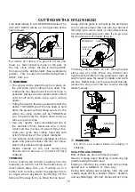
When cutting, operate engine at over 6500 

min-1. Extendedtime of use at low rpm may 

wear out the clutch prematurely.

Cut grass from right to left.

○ 

○ 


WARNING

A cutting attachment can injure while it continues 

to spin after the engine is stopped or power 

control is released. When the unit is turned off , 

make sure the cutting attachment has stopped 

before the unit is set down.
Automatically feeds more nylon cutting line when 

it is tapped at low rpm (not greater than 4500 min-

1).

Summary of Contents for KZ-4000BC-PRO-2S

Page 1: ...ructions CAUTION Read all precautions and instructions in this manual before using this product Keep this manual for future reference Product may vary slightly from picture KZ 4000BC PRO 2S With Japan...

Page 2: ...DUCION 5 MEANINGS OF SYMBOLS 6 SAFETY RULES PRECAUTIONS 7 DESCRIPTION 9 ASSEMBLY 10 RULES FOR SAFE OPERATION 12 OPERATING PROCEDURES 13 CUTTING WITH A NYLON HEAD 15 CUTTING WITH A BLADE 16 MAINTENANCE...

Page 3: ...1 2 3 8 7 5 6 4 3 2 1 6 5 4 9 8 7 1 0 1...

Page 4: ...9 1 0 1 1 1 2 1 3 1 4 1 5 1 6 1 6 3 1 2 1 1 1 5 1 4 1 7 1 6 1 2...

Page 5: ...3...

Page 6: ...2 9 3 0 3 1 2 3 1 3 0 3 5 3 4 3 3 3 7 3 6 3 3 8 4...

Page 7: ...city cm 3 Dry weight kg Cutting attachment Type Dia mm Sound pressure ISO22868 level LpA Equivalent dB A Uncertainty Measured sound ISO22868 power level LwA Racing dB A Uncertainty Measured sound 2000...

Page 8: ...worn when necessary e g when assembling cutting equipment Use anti slip and sturdy footwear Choke Run position Open Choke Start position Closed Before using your machine Read the manual carefully Chec...

Page 9: ...warranty Clean the machine completely especially the fuel tank its surroundings and the air cleaner When refueling be sure to stop the engine and confirm that it is cooled down Never refuel when the e...

Page 10: ...ep the machine away from fire or spark It is believed that a condition called Raynaud s phenomenon which affects the fingers of certain individuals may be brought about by exposure to vibration and co...

Page 11: ...d your unit Use the instructions that apply to your unit 1 Fuel cap 2 Throttle lever 3 Starter handle 4 Blade guard 5 Cutting attachment 6 Drive shaft tube 7 Handle 8 Suspension eyelet 9 Ignition swit...

Page 12: ...e by operating the throttle lever Cover throttle wire and stop cords together with protective tube provided up to air cleaner cover Fig 7 Some models may come with the drive shaft already installed In...

Page 13: ...hen installing a cutting blade make sure that there are no cracks or any damage in it and that the cutting edges are facing the correct direction NOTE When installing cutter holder cap 14 be sure to s...

Page 14: ...EXCEPT OPERATOR ALLOWED 15 METERS RADIUS DANGER ZONE EYE EAR FACE FOOT LEG AND BODY PROTECTION MUST BE WORN BY OPERATOR PERSONS IN ZONE OR RISK BEYOND DANGER ZONE SHOULD WEAR EYE PROTECTION AGAINST TH...

Page 15: ...ea before starting Always wash any spilled fuel from clothing immediately with soap Be sure to check for any fuel leakage after refueling Before fueling clean the tank cap area carefully to ensure tha...

Page 16: ...er harness and hold the machine correctly with both hands If you feel that there is something dangerous separate the brush cutter from your body by pulling the emergency release pinch 22 of the harnes...

Page 17: ...rock particles at high speeds Debris shields on the unit cannot stop objects which bounce or ricochet off hard surfaces For nearly all cutting it is good to tilt the line head so that contact is made...

Page 18: ...with dull cracked or damaged metal blade Before cutting growth inspect for obstructions such as boulders metal stakes or strands of wire from broken fences If an obstruction cannot be removed mark it...

Page 19: ...e The carburetor has one adjustment possibility T Idle speed adjustment screw Idle speed adjustment T speed is correct the cutting attachment will not rotate If adjustment is required close clockwise...

Page 20: ...same direction keeping each half of the line on its own side of the partition Fig 34 4 Push each line into the stopper holes 30 leaving the loose ends approx 10 cm in length Fig 35 5 Insert both loose...

Page 21: ...hat the blade transport guard is undamaged and that it can be securely fi tted Check that nuts and screws are suffi ciently tightened Check that the unit is undamaged and free of defects Check the sta...

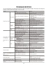
Page 22: ...correct fuel mix 25 1 50 1 Fuel tank contains old fuel offensive odor Replace with new fuel Two cycle oil has not been added Contact Authorized Dealer Service Center Choke lever is in START position...

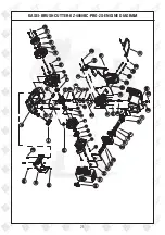
Page 23: ...21 KASEI BRUSH CUTTER KZ 4000BC PRO 2S ENGINE DIAGRAM...

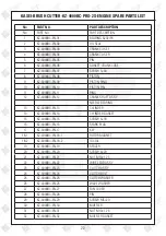
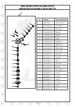
Page 24: ...HAFT ASS Y NEEDLE BEARING 13 KZ 4000BC EN 13 CYLINDER 14 KZ 4000BC EN 14 CYLINDER GASKET 15 KZ 4000BC EN 15 SCREW 5 18 16 KZ 4000BC EN 16 SPARK PLUG 17 KZ 4000BC EN 17 KEY 18 1 KZ 4000BC EN 18 1 ROTOR...

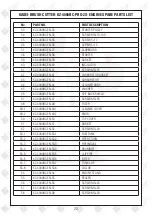
Page 25: ...0BC EN 45 WASHER 46 KZ 4000BC EN 46 SPIT BACK SHIELD 47 KZ 4000BC EN 47 SCREW M5 55 48 KZ 4000BC EN 48 FILTER 49 1 KZ 4000BC EN 49 1 CLEANER COVER 49 2 KZ 4000BC EN 49 2 KNOB 50 KZ 4000BC EN 50 TOP CO...

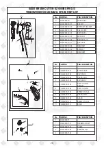
Page 26: ...TA 05 PINION 6 KZ 4000BC TA 06 SCREWM6 35 7 KZ 4000BC TA 07 SCREW M5 12 8 KZ 4000BC TA 08 SCREW M5 8 9 KZ 4000BC TA 09 SCREW M6 8 10 KZ 4000BC TA 10 GEAR CASE 11 KZ 4000BC TA 11 BEARING 12 KZ 4000BC...

Page 27: ...R 2 KZ 4000BC TB 02 HANDGRIP 3 KZ 4000BC TB 03 SCREW M5 25 4 KZ 4000BC TB 04 CAP UPPER 5 KZ 4000BC TB 05 CLAMP RING 6 KZ 4000BC TB 06 LINKER 7 KZ 4000BC TB 07 RUBBER 8 KZ 4000BC TB 08 CAP LOWER No PAR...

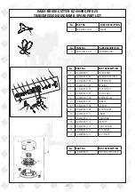
Page 28: ...No PART NO PART DESCRIPTION F KZ 4000BC TF 1 KZ 4000BC TF 01 HARNESS CLAMP 2 KZ 4000BC TF 02 CLAMP 3 KZ 4000BC TF 03 SCREW M5 20 4 KZ 4000BC TF 04 No PART NO PART DESCRIPTION D KZ 4000BC TD LEVER ASS...

Page 29: ...TI 04 STOP RING 15 5 KZ 4000BC TI 05 CLUCH CASE 6 KZ 4000BC TI 06 SCREW M6 20 7 KZ 4000BC TI 07 RUBBER 8 KZ 4000BC TI 08 WASHER 9 KZ 4000BC TI 09 STOP RING 48 10 KZ 4000BC TI 10 LINKER 11 KZ 4000BC T...

Page 30: ...should be cleaned then use closed packaging packaging should be firm Store the machine in dry place For transportation safety The machine should comply with ISTA Meaning of crossed out wheeled dustbin...

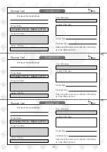
Page 31: ...ct Name Product Serial No Invoice DN No Date of Delivery Dealer s Office Seal Dealer Sign Customer Sign I We accept the terms and conditions of Warranty as in the Warranty Card DEALER S COPY Warranty...

Page 32: ...le using the pressure washers to draw water which is contaminated with dust solvents eg paint thinners gasoline oil etc vii Repair done by unauthorized service people viii Those parts subject to wear...

Page 33: ...e Carburetor Tuning Check and Sharpen the cutting Tools Start and Check the Noise Vibration Loosen Fasteners etc Product familiarization on Usage Routine maintenance and Storage Customer Signature Con...

Page 34: ...32 Small Maintenance Big Savings Small Maintenance Big Savings Small Maintenance Big Savings...

Page 35: ......

Page 36: ...PVT LTD Annapurna House 1 1G 7th Cross New Guddadahalli Mysore Road Bangalore 560 026 Customer Care 1800 425 3036 email marketing ratnagiriimpex com www ratnagiriimpex com AN ISO 9001 2008 CERTIFIED C...

Reviews: