background image

CUTTING WITH A NYLON HEAD

15

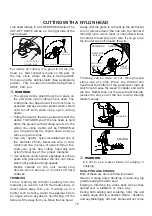
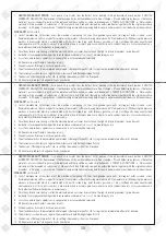
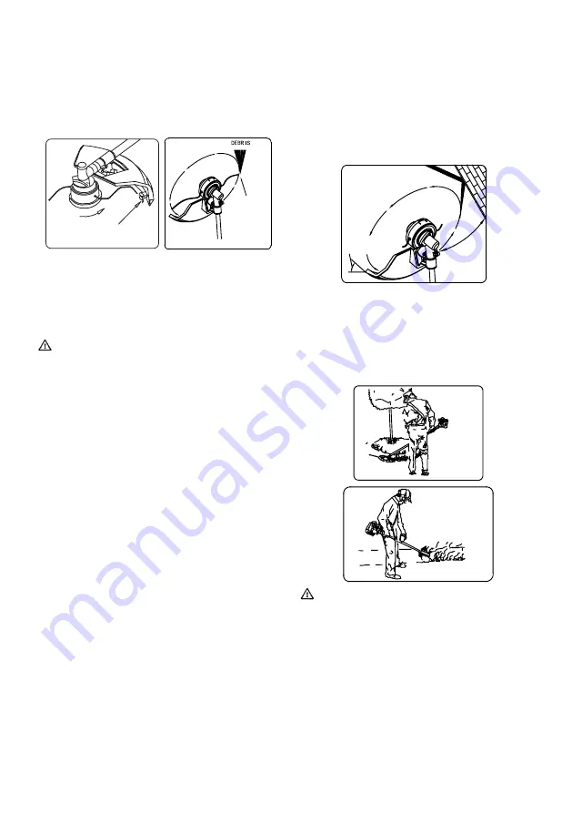
Line head rotates in a CLOCKWISE direction.The 

CUT-OFF KNIFE will be on  the right side of the 

debris shield.

slowly until the grass is cut right up the barrier,but 

do not jam(overfeed )the line into the barrier.If 

trimming up to a wire mesh or chain linked fence 

be careful to feed only up to wire. If you go to far 

the line will snap off around  the wire.

ON LEFT SIDE

CUT-OFF KNIFE

CUT ON


COUNTER CLOCK WISE ROTATION  

 THIS SIDE


WARNING

The proper debris shield must be in place on 

the unit when nylon cutting line is used. The 

cutting line can flap around if too much line is 

exposed. Always use the plastic debri shield 

with cut-off knife when using nylon cutting 

heads.

Tilting the head to the wrong side will shoot the  

debris  TOWARDS you.If  the line head  is held 

flat to the ground so that cutting occurs on  the  

whole  line  circle,  debris  will  be THROWN at 

you, drag will slow the engine down, and you 

will use up a lot of line.

Use only  quality  nylon monofilament line of 

the  diameter 2.5mm. Never use wire  or wire-

reinforced line in place of nylon trimmer line. 

Load your  nylon  line  cutting  head only with 

nylon trimmer line of  the  proper  diameter

.

Use extreme caution when operating over bare 

spots and gravel,because the line can throw 

small rock particles at high speeds.

Debris  shields  on  the  unit  cannot stop 

objects which bounce or ricochet off hard 

surfaces.

For nearly all cutting, it is good to tilt the line  

head  so  that contact is made on the part  of 

the  line  circle  where  the line is moving AWAY 

from you and the  debris shield. (See  appropraite  

picture)   This  results in the debris being thrown 

AWAY  from you.

○ 

○ 

○ 

○ 

TRIMMING

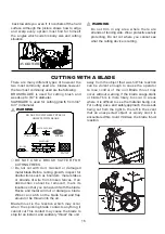
This is feeding the trimmer carefully into the 

material you wish to cut.Tilt the head slowly to 

direct debris away from you. If cutting up to a  

barrier such as fence, wallor tree,approach from  

an angle where anydebris ricocheting off the  

barrier will fly away from you.Move the line head  

TO WALL

ANGLE

GROUND

RAISED

KNIFE SIDE

TRIMMING

ANGLE TO

DEBRIS

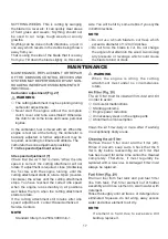
Trimming can be done  to cut  through weed 

stems one at a time. Place  the trimmer line 

head near the bottom of the weed-never high up 

which could cause the weed to chatter and catch 

the line. Rather than cut the weed right through, 

justuse the very end of the line to wear through 

thestem slowly.

SCALPING

EDGING


WARNING

Do not to use a steel blade for edging or 

scalping.

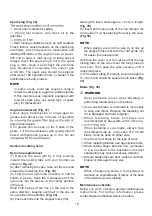
SCALPING AND ENGING:

Both of these are done with the line head

tilted at a steep angle Scalping is removing top 

growth leaving the earth bear.

Edging is trimming the grass back where ithas 

spread over  a  sidewalk  or  drive  way.

During both edging and scalping, hold  the unit 

a steep angle and in a position where

  t

hedibris, 

and any dislodging  dirt  and  stones,will not come 

Summary of Contents for KZ-4000BC-PRO-2S

Page 1: ...ructions CAUTION Read all precautions and instructions in this manual before using this product Keep this manual for future reference Product may vary slightly from picture KZ 4000BC PRO 2S With Japan...

Page 2: ...DUCION 5 MEANINGS OF SYMBOLS 6 SAFETY RULES PRECAUTIONS 7 DESCRIPTION 9 ASSEMBLY 10 RULES FOR SAFE OPERATION 12 OPERATING PROCEDURES 13 CUTTING WITH A NYLON HEAD 15 CUTTING WITH A BLADE 16 MAINTENANCE...

Page 3: ...1 2 3 8 7 5 6 4 3 2 1 6 5 4 9 8 7 1 0 1...

Page 4: ...9 1 0 1 1 1 2 1 3 1 4 1 5 1 6 1 6 3 1 2 1 1 1 5 1 4 1 7 1 6 1 2...

Page 5: ...3...

Page 6: ...2 9 3 0 3 1 2 3 1 3 0 3 5 3 4 3 3 3 7 3 6 3 3 8 4...

Page 7: ...city cm 3 Dry weight kg Cutting attachment Type Dia mm Sound pressure ISO22868 level LpA Equivalent dB A Uncertainty Measured sound ISO22868 power level LwA Racing dB A Uncertainty Measured sound 2000...

Page 8: ...worn when necessary e g when assembling cutting equipment Use anti slip and sturdy footwear Choke Run position Open Choke Start position Closed Before using your machine Read the manual carefully Chec...

Page 9: ...warranty Clean the machine completely especially the fuel tank its surroundings and the air cleaner When refueling be sure to stop the engine and confirm that it is cooled down Never refuel when the e...

Page 10: ...ep the machine away from fire or spark It is believed that a condition called Raynaud s phenomenon which affects the fingers of certain individuals may be brought about by exposure to vibration and co...

Page 11: ...d your unit Use the instructions that apply to your unit 1 Fuel cap 2 Throttle lever 3 Starter handle 4 Blade guard 5 Cutting attachment 6 Drive shaft tube 7 Handle 8 Suspension eyelet 9 Ignition swit...

Page 12: ...e by operating the throttle lever Cover throttle wire and stop cords together with protective tube provided up to air cleaner cover Fig 7 Some models may come with the drive shaft already installed In...

Page 13: ...hen installing a cutting blade make sure that there are no cracks or any damage in it and that the cutting edges are facing the correct direction NOTE When installing cutter holder cap 14 be sure to s...

Page 14: ...EXCEPT OPERATOR ALLOWED 15 METERS RADIUS DANGER ZONE EYE EAR FACE FOOT LEG AND BODY PROTECTION MUST BE WORN BY OPERATOR PERSONS IN ZONE OR RISK BEYOND DANGER ZONE SHOULD WEAR EYE PROTECTION AGAINST TH...

Page 15: ...ea before starting Always wash any spilled fuel from clothing immediately with soap Be sure to check for any fuel leakage after refueling Before fueling clean the tank cap area carefully to ensure tha...

Page 16: ...er harness and hold the machine correctly with both hands If you feel that there is something dangerous separate the brush cutter from your body by pulling the emergency release pinch 22 of the harnes...

Page 17: ...rock particles at high speeds Debris shields on the unit cannot stop objects which bounce or ricochet off hard surfaces For nearly all cutting it is good to tilt the line head so that contact is made...

Page 18: ...with dull cracked or damaged metal blade Before cutting growth inspect for obstructions such as boulders metal stakes or strands of wire from broken fences If an obstruction cannot be removed mark it...

Page 19: ...e The carburetor has one adjustment possibility T Idle speed adjustment screw Idle speed adjustment T speed is correct the cutting attachment will not rotate If adjustment is required close clockwise...

Page 20: ...same direction keeping each half of the line on its own side of the partition Fig 34 4 Push each line into the stopper holes 30 leaving the loose ends approx 10 cm in length Fig 35 5 Insert both loose...

Page 21: ...hat the blade transport guard is undamaged and that it can be securely fi tted Check that nuts and screws are suffi ciently tightened Check that the unit is undamaged and free of defects Check the sta...

Page 22: ...correct fuel mix 25 1 50 1 Fuel tank contains old fuel offensive odor Replace with new fuel Two cycle oil has not been added Contact Authorized Dealer Service Center Choke lever is in START position...

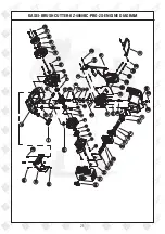
Page 23: ...21 KASEI BRUSH CUTTER KZ 4000BC PRO 2S ENGINE DIAGRAM...

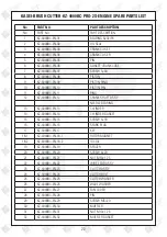
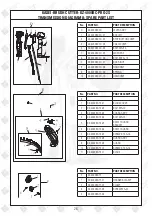
Page 24: ...HAFT ASS Y NEEDLE BEARING 13 KZ 4000BC EN 13 CYLINDER 14 KZ 4000BC EN 14 CYLINDER GASKET 15 KZ 4000BC EN 15 SCREW 5 18 16 KZ 4000BC EN 16 SPARK PLUG 17 KZ 4000BC EN 17 KEY 18 1 KZ 4000BC EN 18 1 ROTOR...

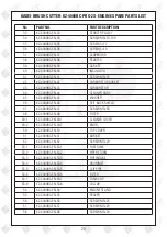
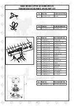
Page 25: ...0BC EN 45 WASHER 46 KZ 4000BC EN 46 SPIT BACK SHIELD 47 KZ 4000BC EN 47 SCREW M5 55 48 KZ 4000BC EN 48 FILTER 49 1 KZ 4000BC EN 49 1 CLEANER COVER 49 2 KZ 4000BC EN 49 2 KNOB 50 KZ 4000BC EN 50 TOP CO...

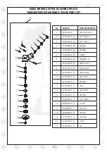
Page 26: ...TA 05 PINION 6 KZ 4000BC TA 06 SCREWM6 35 7 KZ 4000BC TA 07 SCREW M5 12 8 KZ 4000BC TA 08 SCREW M5 8 9 KZ 4000BC TA 09 SCREW M6 8 10 KZ 4000BC TA 10 GEAR CASE 11 KZ 4000BC TA 11 BEARING 12 KZ 4000BC...

Page 27: ...R 2 KZ 4000BC TB 02 HANDGRIP 3 KZ 4000BC TB 03 SCREW M5 25 4 KZ 4000BC TB 04 CAP UPPER 5 KZ 4000BC TB 05 CLAMP RING 6 KZ 4000BC TB 06 LINKER 7 KZ 4000BC TB 07 RUBBER 8 KZ 4000BC TB 08 CAP LOWER No PAR...

Page 28: ...No PART NO PART DESCRIPTION F KZ 4000BC TF 1 KZ 4000BC TF 01 HARNESS CLAMP 2 KZ 4000BC TF 02 CLAMP 3 KZ 4000BC TF 03 SCREW M5 20 4 KZ 4000BC TF 04 No PART NO PART DESCRIPTION D KZ 4000BC TD LEVER ASS...

Page 29: ...TI 04 STOP RING 15 5 KZ 4000BC TI 05 CLUCH CASE 6 KZ 4000BC TI 06 SCREW M6 20 7 KZ 4000BC TI 07 RUBBER 8 KZ 4000BC TI 08 WASHER 9 KZ 4000BC TI 09 STOP RING 48 10 KZ 4000BC TI 10 LINKER 11 KZ 4000BC T...

Page 30: ...should be cleaned then use closed packaging packaging should be firm Store the machine in dry place For transportation safety The machine should comply with ISTA Meaning of crossed out wheeled dustbin...

Page 31: ...ct Name Product Serial No Invoice DN No Date of Delivery Dealer s Office Seal Dealer Sign Customer Sign I We accept the terms and conditions of Warranty as in the Warranty Card DEALER S COPY Warranty...

Page 32: ...le using the pressure washers to draw water which is contaminated with dust solvents eg paint thinners gasoline oil etc vii Repair done by unauthorized service people viii Those parts subject to wear...

Page 33: ...e Carburetor Tuning Check and Sharpen the cutting Tools Start and Check the Noise Vibration Loosen Fasteners etc Product familiarization on Usage Routine maintenance and Storage Customer Signature Con...

Page 34: ...32 Small Maintenance Big Savings Small Maintenance Big Savings Small Maintenance Big Savings...

Page 35: ......

Page 36: ...PVT LTD Annapurna House 1 1G 7th Cross New Guddadahalli Mysore Road Bangalore 560 026 Customer Care 1800 425 3036 email marketing ratnagiriimpex com www ratnagiriimpex com AN ISO 9001 2008 CERTIFIED C...

Reviews: