background image

936.2391/

D

/0

8

06/3.12e

6. Mounting site


Attention!


•  Never install the antenna below overhead power lines. It is possible that the required safety  

  distance is not kept. Furthermore, make sure that the lateral distance to all other electrical sy-

  stems is at least 1 m.


  Danger to life exists if you or the antenna come into contact with live parts.


•  Do not install the antenna on buildings with an easily infl ammable roof (straw, reed or similar


  material). Fire hazard exists since the antenna is subject to static charge and lightning.

The selection of the right mounting site for your fl at antenna is important in order to ensure safe and satisfactory

operation. Therefore, observe the following:

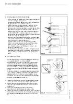
a)  ”Visibility“ of the satellite

  The antenna must have an unobstructed ”visibility“ to the south (+/- 20°).

  A few satellites (e. g. TÜRKSAT 1C, HISPASAT 1A/1B) require an angle larger than +/- 20° looked at from the 

south (Azimuth). The horizontal elevation angle must be 30°.

  Unobstructed ”visibility“ means that there must be no obstacle (such as trees, buildings, roofs, balconies or simi-

lar obstacles) between the antenna and the satellite.

  Obstacles of this kind can impair the reception or even make reception impossible.

b)  Secure installation


The decisive factor for choosing the mounting site for your fl at antenna is not – when compared with a standard

  receiving antenna – the installation height above ground, but the unobstructed ”visibility“ of the satellite. This 

means that the installation need not effected on the roof of a house.

  The antenna can be installed in the garden, on a terrace, on a balcony, on a facade or on a garage.


  Therefore, if other possibilities for the installation exist, do not install on the roof. It will mean less work for you 

and additionally, the dangers connected with working on a roof are much smaller.


Attention


•  The installation work can create problems for your health and life.


  Therefore:


•  The mounting procedure described here demands skill and a knowledge of how the antenna


  behaves when being exposed to atmospheric conditions. If you don´t have the required qualifi -

  cations, ask a specialist to do the installation work.


•  When working on the roof or near to drop–away sites, use a safety belt.


•  Make sure that the roof will support your weight. Wear non-slip shoes.


•  Only use ladders or other climbing aids that are in perfect condition.


•  If passers-by can be hurt by parts falling down, block the dangerous area.


•  Watch out for overhead power lines. Contact with these means danger to life!


•  Never work on antenna systems when there is a thunderstorm – Danger to life!

7. Installation of the antenna

Summary of Contents for 216197

Page 1: ...antenne gilt eine Antenne mit einer freien Mast l nge von h chstens 6 m und einem Einspannmoment von bis zu 1650 Nm siehe auch DIN 4131 Die Flachantenne BAS 62 ist in ihrer Ausf hrung nur f r die sta...

Page 2: ...er Windgeschwindigkeit von 150 km h Spannbereichs Durchmesser mm 38 60 Gewicht kg 6 9 5 Wichtige Hinweise Bevor Sie die Flachantenne montieren anschlie en oder verwenden beachten Sie unbedingt die Hin...

Page 3: ...ensatz zu Stabantennen ist bei Ihrer Flachantenne wie generell bei Satelliten Antennen nicht die Mon tageh he ber Grund bedeutend sondern die freie Sicht zum Satelliten Daher kann sich ein geeigneter...

Page 4: ...enkrecht steht Andernfalls kann die Ausrich tung der Antenne auf den Satelliten zu Schwierigkeiten f hren b Polarisation einstellen Satellitensignale werden mit einem bestimmten Richtungs sinn ausgese...

Page 5: ...18 Belgien 25 5 4 5 9 5 3 1 2 10 Bulgarien 17 5 15 17 18 22 30 D nemark 19 5 1 5 4 0 3 5 6 12 Deutschland 22 5 0 5 0 2 5 5 7 5 15 England 27 7 5 15 8 7 5 5 3 5 Frankreich 30 7 5 15 7 6 3 2 8 Finnland...

Page 6: ...mmen Sie Ihr TV Ger t auf jenen Kanal ab auf den der Ausgangskanal des Satelliten Receivers eingerichtet ist Speichern Sie diesen Kanal auf einem freien TV Programm Speicherplatz 4 Um die Antenne auf...

Page 7: ...uttern wechselseitig fest Die Fl gelmuttern sind ausreichend fest wenn Sie sie erst handfest anziehen und dann mit einem Gabelschl ssel Schl sselweite 13 jeweils eine Umdre hung weiter drehen 8 Ziehen...

Page 8: ...urch wenn Sie nicht selbst Fachkraft mit entsprechenden Kenntnissen sind Die hier abgedruckten Hinweise sind keine Aufforderung an Nichtfachleute Erdungs und Blitzschutzarbeiten in eigener Verantwortu...

Page 9: ...26 8 5 1 2 Hamburg 168 6 28 3 5 1 4 176 3 28 8 5 1 4 198 4 27 3 5 1 2 157 7 26 6 5 1 2 Hannover 168 2 29 5 5 1 4 175 9 30 1 5 1 4 198 4 28 6 5 1 4 157 2 27 7 5 1 4 Kassel 167 6 30 6 5 175 4 31 2 5 19...

Page 10: ...6 26 6 5 1 2 Clermont Ferr 158 02 34 97 4 3 4 166 27 36 42 4 1 2 191 19 31 30 5 146 8 31 8 5 Dijon 161 08 33 88 4 3 4 169 25 35 06 4 3 4 193 55 34 73 4 3 4 149 8 31 1 5 Le Havre 155 50 30 37 5 1 4 16...

Page 11: ...1 36 9 4 1 2 Roma 170 02 41 14 4 1 4 179 25 41 62 4 1 4 205 27 38 43 4 1 2 157 2 39 4 1 2 Sassari 163 92 41 66 4 1 4 173 20 42 69 4 200 27 40 89 4 1 4 151 3 38 8 4 1 2 Taranto 176 90 43 13 4 186 43 4...

Page 12: ...8 39 80 4 1 4 135 7 29 4 5 1 4 Granada 145 19 40 71 4 1 4 153 76 43 51 4 182 34 46 89 3 3 4 129 9 40 4 1 4 Ibiza 152 97 41 32 4 1 4 161 95 43 38 4 190 18 44 47 4 141 2 37 1 4 1 2 La Coruna 142 68 32 8...

Page 13: ...e of the BAS 62 The household antenna is de ned as an antenna with a free mast length of 6 m max and a xing moment of up to 1650 Nm at the xing point see DIN 4131 2 Scope of delivery Fig A The at ante...

Page 14: ...of 150 km h Clamping range mm 38 60 Weight kg 6 9 5 Important information Before you begin to install connect or utilise the antenna observe the information you nd in these mounting instructions If yo...

Page 15: ...osing the mounting site for your at antenna is not when compared with a standard receiving antenna the installation height above ground but the unobstructed visibility of the satellite This means that...

Page 16: ...al position otherwise the alignment of the antenna to the satellite can create problems b Setting the polarisation Satellite signals are transmitted in a de nite direction sense which means they are p...

Page 17: ...10 18 Belgium 25 5 4 5 9 5 3 1 2 10 Bulgaria 17 5 15 17 18 22 30 Croatia 23 5 4 5 4 5 7 10 13 22 Czech Rep 20 4 3 5 6 9 13 21 Denmark 19 5 1 5 4 0 3 5 6 12 Finland 5 8 10 12 13 15 France 30 7 5 15 7 6...

Page 18: ...of the satellite receiver has been tuned Save this channel on a free programme position on your TV set 4 Alignment to the desired satellite requires that you select a corresponding programme position...

Page 19: ...nough if they are first tightened slightly and then fully tightened with the aid of an open ended spanner 13 mm jaw size 8 Next slightly tighten the left and the right elevation screws of the mast cla...

Page 20: ...adequately If you are not a specialist abstain from installing such systems The information you nd in this instruction is not an invitation for unexperienced people to effect the installation on one s...

Page 21: ...5 1 2 Hamburg 168 6 28 3 5 1 4 176 3 28 8 5 1 4 198 4 27 3 5 1 2 157 7 26 6 5 1 2 Hannover 168 2 29 5 5 1 4 175 9 30 1 5 1 4 198 4 28 6 5 1 4 157 2 27 7 5 1 4 Kassel 167 6 30 6 5 175 4 31 2 5 198 3 2...

Page 22: ...147 6 26 6 5 1 2 Clermont Ferr 158 02 34 97 4 3 4 166 27 36 42 4 1 2 191 19 31 30 5 146 8 31 8 5 Dijon 161 08 33 88 4 3 4 169 25 35 06 4 3 4 193 55 34 73 4 3 4 149 8 31 1 5 Le Havre 155 50 30 37 5 1...

Page 23: ...1 36 9 4 1 2 Roma 170 02 41 14 4 1 4 179 25 41 62 4 1 4 205 27 38 43 4 1 2 157 2 39 4 1 2 Sassari 163 92 41 66 4 1 4 173 20 42 69 4 200 27 40 89 4 1 4 151 3 38 8 4 1 2 Taranto 176 90 43 13 4 186 43 42...

Page 24: ...35 7 29 4 5 1 4 Granada 145 19 40 71 4 1 4 153 76 43 51 4 182 34 46 89 3 3 4 129 9 40 4 1 4 Ibiza 152 97 41 32 4 1 4 161 95 43 38 4 190 18 44 47 4 141 2 37 1 4 1 2 La Coruna 142 68 32 84 5 150 25 35 5...

Page 25: ...uble est une antenne selon DIN 4131 dont la longueur libre de m t ne d passe pas de 6 m et qui a un moment de exion de 1650 Nm au maximum sur le point de xation Comme mentionn ci dessus l antenne plan...

Page 26: ...ur la terre il faut multiplier la charge au vent par le facteur 1 37 Cela correspond une vitesse de vent de 150 km h Diam tre de serrage mm 38 60 Poids kg 6 9 5 Remarques importantes Avant de proc der...

Page 27: ...our votre antenne plane c est la visibilit directe qui est importante Pour cette raison il est bien possible que le lieu de montage puisse tre dans le jardin sur une terrasse sur un balcon sur une fa...

Page 28: ...e Sinon le positionnement de l antenne sur le satellit pourra t cr er un probl me b Ajustage de polarisation Les signaux satellite sont transmis avec un certain sens de direction c d ils sont polaris...

Page 29: ...5 5 7 5 15 Angleterre 27 7 5 15 8 7 5 5 3 5 Autriche 22 3 5 3 2 5 5 8 10 18 Belgique 25 5 4 5 9 5 3 1 2 10 Bulgarie 17 5 15 17 18 22 30 Croatie 23 5 4 5 4 5 7 10 13 22 Danemark 19 5 1 5 4 0 3 5 6 12 E...

Page 30: ...eur de votre r cepteur r glez votre t l viseur sur le m me canal Sauvegardez ce canal dans un emplacement de m moire libre 4 Pour le positionnement de l antenne sur le satellite d sir s lectionnez au...

Page 31: ...pour l optimisation de l antenne mais elle doit tre prise en consid ration pour le serrage ult rieur 7 Serrez en croix les crous oreilles Les crous sont bien fix es si vous les serrez d abord l g reme...

Page 32: ...c dente n est pas d invitation au profane d effectuer sous sa responsabilit de telles installa tions mais sert de guide pour le sp cialiste charg par vous pour ce travail syst me de mise la terre ou...

Page 33: ...8 6 28 3 5 1 4 176 3 28 8 5 1 4 198 4 27 3 5 1 2 157 7 26 6 5 1 2 Hannover 168 2 29 5 5 1 4 175 9 30 1 5 1 4 198 4 28 6 5 1 4 157 2 27 7 5 1 4 Kassel 167 6 30 6 5 175 4 31 2 5 198 3 29 7 5 1 4 156 5 2...

Page 34: ...6 6 5 1 2 Clermont Ferr 158 02 34 97 4 3 4 166 27 36 42 4 1 2 191 19 31 30 5 146 8 31 8 5 Dijon 161 08 33 88 4 3 4 169 25 35 06 4 3 4 193 55 34 73 4 3 4 149 8 31 1 5 Le Havre 155 50 30 37 5 1 4 163 22...

Page 35: ...8 1 36 9 4 1 2 Roma 170 02 41 14 4 1 4 179 25 41 62 4 1 4 205 27 38 43 4 1 2 157 2 39 4 1 2 Sassari 163 92 41 66 4 1 4 173 20 42 69 4 200 27 40 89 4 1 4 151 3 38 8 4 1 2 Taranto 176 90 43 13 4 186 43...

Page 36: ...4 3 4 153 83 36 39 4 1 2 178 98 39 80 4 1 4 135 7 29 4 5 1 4 Granada 145 19 40 71 4 1 4 153 76 43 51 4 182 34 46 89 3 3 4 129 9 40 4 1 4 Ibiza 152 97 41 32 4 1 4 161 95 43 38 4 190 18 44 47 4 141 2 3...

Page 37: ...realizzazione 2 Dotazione gura A L antenna piatta BAS 62 viene fornita in stato premontato in fabbrica Soltanto i presenti componenti riepilogati nella gura A costituiscono un eccezione 3 Accessori ra...

Page 38: ...anti Prima di montare collegare oppure utilizzare l antenna piatta si raccomanda di osservare assolutamente le informazioni riportate nelle presenti istruzioni per l uso In una mancata osservanza di q...

Page 39: ...anche nelle antenne satellitari non determinante l altezza del luogo di montaggio dal suolo bens la visuale libera verso il satellite Pertanto un luogo di montaggio adatto pu essere per esempio anche...

Page 40: ...icazioni al centraggio dell antenna sul satellite desiderato b Regolazione della polarizzazione I segnali satellitari vengono trasmessi con una determinata direzione cio sono polarizzati L antenna pia...

Page 41: ...Austria 22 3 5 3 2 5 5 8 10 18 Belgio 25 5 4 5 9 5 3 1 2 10 Bulgaria 17 5 15 17 18 22 30 Croazia 23 5 4 5 4 5 7 10 13 22 Danimarca 19 5 1 5 4 0 3 5 6 12 Finlandia 5 8 10 12 13 15 Francia 30 7 5 15 7...

Page 42: ...vate questo canale in un posto di salvataggio libero per i programmi televisivi 4 Per centrare l antenna sul satellite desiderato regolare il posto del programma nel rispettivo ricevitore satellitare...

Page 43: ...chiave a forcella ampiezza 13 girare avanti rispettivamente di un giro 8 Girare successivamente a mano in senso antiorario e orario nella fascetta del traliccio le viti di elevazione Afferrare a tal...

Page 44: ...elettrotecnici e delle rispettive nozioni Le informazioni qui riportate non sono un invito rivolto a persone non specializzate ad eseguire lavori di messa a terra o ai parafulmini su propria responsab...

Page 45: ...0 5 1 2 161 9 26 8 5 1 2 Hamburg 168 6 28 3 5 1 4 176 3 28 8 5 1 4 198 4 27 3 5 1 2 157 7 26 6 5 1 2 Hannover 168 2 29 5 5 1 4 175 9 30 1 5 1 4 198 4 28 6 5 1 4 157 2 27 7 5 1 4 Kassel 167 6 30 6 5 17...

Page 46: ...26 6 5 1 2 Clermont Ferr 158 02 34 97 4 3 4 166 27 36 42 4 1 2 191 19 31 30 5 146 8 31 8 5 Dijon 161 08 33 88 4 3 4 169 25 35 06 4 3 4 193 55 34 73 4 3 4 149 8 31 1 5 Le Havre 155 50 30 37 5 1 4 163 2...

Page 47: ...8 1 36 9 4 1 2 Roma 170 02 41 14 4 1 4 179 25 41 62 4 1 4 205 27 38 43 4 1 2 157 2 39 4 1 2 Sassari 163 92 41 66 4 1 4 173 20 42 69 4 200 27 40 89 4 1 4 151 3 38 8 4 1 2 Taranto 176 90 43 13 4 186 43...

Page 48: ...4 153 83 36 39 4 1 2 178 98 39 80 4 1 4 135 7 29 4 5 1 4 Granada 145 19 40 71 4 1 4 153 76 43 51 4 182 34 46 89 3 3 4 129 9 40 4 1 4 Ibiza 152 97 41 32 4 1 4 161 95 43 38 4 190 18 44 47 4 141 2 37 1...

Reviews: