background image

www.kathrein-ds.com | support@kathrein-ds.com  

936500099/b/A4/STM/1121/DE | Subject to amendment.

KATHREIN Digital Systems GmbH   |   Anton-Kathrein-Str. 1–3   |   83022 Rosenheim   |   Germany   |   Phone +49 731 270 909 70

For your notes

Electronic equipment

Electronic equipment must not be disposed of in domestic waste. According to directive 2012/19/EU OF THE EUROPEAN 

PARLIAMENT AND COUNCIL of 04 July 2012 on waste electrical and electronic equipment, it must be disposed of profes-

sionally. At the end of its service life, take this unit to a designated public collection point for disposal.

Disposal

Summary of Contents for 237500017

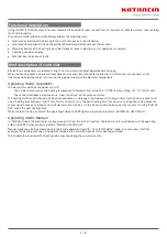
Page 1: ...er 70 90 mm 10 x Cable ties 360 mm long 4 x Caps M16 1 x Cable gland M32 x 1 5 English instructions for use Transport and storage If possible transport and store the temperature controller in the original packaging Store the temperature controller in a dry location and protect it against mechanical damage The ESO 99 S is a temperature controller for ESO 120 124 180 H and ESO 124 180 HL reflector h...

Page 2: ...k in the event of contact with electrical equipment Correct performance of the installation and electrical connection is a crucial safety factor Observe the installation conditions and steps described as precisely as possible Modifications to the electrical installation may only be carried out by a specialist electrician Do not make any modifica tions yourself Intended use Do not use the ESO 99 S ...

Page 3: ...ure and heating temperature fall below the set value P 4 C SRR factory setting 40 C ELTC 21 and The sensor electrodes detect moisture snow ice or frost on the antenna surface The heating switches off when one of the above conditions is no longer true However the integral timer function can be used to set a post heating time between 1 and 10 min factory setting 5 min The post heating time thus cove...

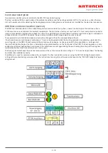
Page 4: ...These parameters are determined once and cannot be changed without the corresponding software If both conditions are met temperature below 4 C and ice build up detected the heating controller is enabled by a potential free switching relay in the SRR 200 and heating of the antenna surface begins As soon as one of the two conditions is no longer met the post heating time begins the time is adjustabl...

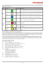
Page 5: ...ion If the sensor fails or there is a sensor short circuit the heating is switched off Operation is very easy After switching on the device type number C 2 appears followed around three seconds later by the meas ured actual value Briefly pressing the P button displays Set followed by the setpoint display which automatically reverts after 5 seconds Pressing the P button for around 3 seconds opens t...

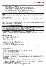
Page 6: ...should be repeated after replacement of a defective heating plate Heating functional test 1 Measure the mains input voltage 230 VAC 6 10 2 Green Status and Operation LEDS light up 3 Set switch 1S1 to Manual ON 4 Yellow Heating Manual LED flashes 5 Measure the heating circuit voltage and heating circuit current at terminals X1 1 10 During this time the ELTC 21 monitors the heating temperature Chang...

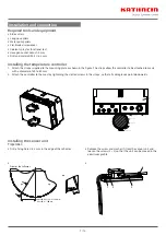
Page 7: ...er to be attached to masts with a diameter of 60 to 85 mm 2 Attach the controller to the mast by tightening the slotted screws in the straps so that all cable glands point downwards Control unit Tensioning screw Mounting plate Tensioning strap Antenna mast Lid Installing the sensor unit Drill a fixing hole 6 2 mm in the edge of the reflector A A A A Front of the reflector X CAS 120 CAS 124 X 280 m...

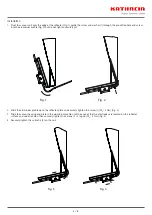
Page 8: ...n securely yet Fig 1 Fig 2 2 Slide the aluminium profile up to the reflector plate and securely tighten the screw 1 MA 5 Nm Fig 3 3 Slide the sensor housing and plate in the aluminium profile until the ends of the two electrodes are located on the reflector surface and under tension then securely tighten the screws 2 3 again MA 5 Nm Fig 4 4 Securely tighten the cable tie 4 on the unit Fig 3 Fig 4 ...

Page 9: ...se measurements should also be performed after replacement of a defective heater Refer to the oper ating instructions for the corresponding reflector heater for details 4 The cables are connected as shown in the Connection diagram on page 11 Only connect the electrical system to the voltage spec ified on the rating plate Non compliance can destroy the heating due to overheating or fire Connecting ...

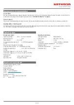
Page 10: ...ensions 360 x 254 x 165 mm Weight 5 3 kg Cable inlets 3 x M12 5 x M16 1 x M32 M25 Permissible ambient temperature 30 to 60 C Recommended installation temperature 5 to 20 C Protection class IP66 Electrical data Operating voltage 230 V 6 10 50 60 Hz Breaking capacity 16 A Alarm contact 8 A 230 V Temperature measuring input 2 x PT 100 temperature sensor Moisture measuring input 2 rod probe Activation...

Page 11: ... 14 13 10 K1 11 ESO 180 HL ESO 180 H Optional ESO 90 H ESO 120 H ESO 124 H X1 1 E1 1 E1 2 4 3 E1 4 5 E1 PE 6 7 E1 8 ESO 126 ESO 129 Beheizung für Speisesystem Halterungen 9 E1 10 PE 2 PE 3 PE 4 PE 5 PE 1 Fühler Heizungstemperatur ESO 124 HL 1 NST 255 2 Stabsonde EL rosa GND grau 22 21 132 131 X1 Alarm Ruhestromprinzip im Fehlerfall geöffnet Fernwirkkontakt manuell Ein 5 30V weiss grün braun 1K1 A1...

Page 12: ... 909 70 For your notes Electronic equipment Electronic equipment must not be disposed of in domestic waste According to directive 2012 19 EU OF THE EUROPEAN PARLIAMENT AND COUNCIL of 04 July 2012 on waste electrical and electronic equipment it must be disposed of profes sionally At the end of its service life take this unit to a designated public collection point for disposal Disposal ...

Reviews: