36 of 112
Connecting the Reader
12.2
Connecting the Antenna
NOTICE
Risk of malfunction!
When using a cable not suitable for the impedance of 50 Ohm, the performance of the r
eader will be
severely limited by the mismatch. If the mismatch is large, the reader may indicate a fault.
►
Only use cable suitable for the impedance (50 Ohm).
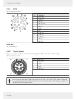
For the connection to the RFID antennas, the reader has four antenna connections that are of the reverse TNC design.
►
Only use the cable from the accessories or equivalent cable for this connection.
12.3
T
urning the Reader On and Off
►
Connect the reader to the power supply via a
PWR
or to a PoE source according to the 802.3at standard via
LAN /POE
input.
➯
The reader is on.
12.4
Reading the PWR LED Indications
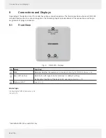
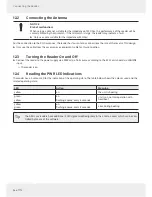
The reader has a 2-colour LED for the indication of the operating state. The table below shows the colours used and the
related operating state:
LED
Action
Meaning
yellow
on
the unit is booting
green
yellow
on
flashing appr
ox. every 8 seconds
unit is on, normal operation with
heartbeat
yellow
green
on
flashing appr
ox. every 8 seconds
error during booting
Tip
The ARU 3xxx readers have additional 4 LEDs (green/red/red/green) in the antenna cover which can be con-
trolled by means of the software.

