Page 37
Copyright © 2012 Kato Engineering, Inc. All rights reserved
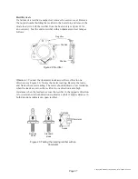
Figure 22: Rectifi er
Negative
Positive
Positive
Reverse
diode
Standard
diode
Anode
Cathode
Ohmmeter
Figure 23: Testing the rotating rectifi er with an
ohmmeter
Rectifi er tests
If a failure of a rectifi er is suspected, remove the exciter cover. Remove
the nut and washer holding the rectifi er in the heat sink, and remove the
diode lead wire. Lift the rectifi er from the heat sink (see fi gure 22 for
an overview). Test the entire rectifi er with an ohmmeter or test lamp as
follows:
Ohmmeter: Connect the ohmmeter leads across the rectifi er in one
direction (see Figure 23). Notice the meter reading. Reverse the leads,
and Notice the meter reading. The meter should indicate a low resistance
when the leads are across the rectifi er in one direction and a high
resistance when the leads are across the rectifi er in the opposite direction.
A low resistance in both directions indicates a short. A high resistance in
both directions indicates an open rectifi er.


