background image

 WARNING

  You must read and understand this manual before operating 

or servicing this crane.

  If you do not do so, you may cause serious injury or death 

including damage to the equipment etc.

  All people who come into contact with this crane must read 

and be familiar with the contents of this manual. Keep it in 
the crane so it will be available to anybody who needs it.

  If you need a copy of this manual in another language, ask 

your authorised KATO dealer.

218711

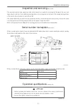
Applicable serial No.: 0051

Machine Section

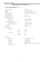
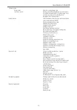
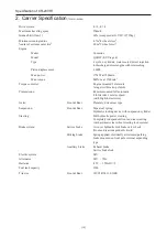
Summary of Contents for PREMIUM CITYRANGE CR-200RF

Page 1: ...including damage to the equipment etc All people who come into contact with this crane must read and be familiar with the contents of this manual Keep it in the crane so it will be available to anybody who needs it If you need a copy of this manual in another language ask your authorised KATO dealer 218711 Applicable serial No 0051 Machine Section ...

Page 2: ...218711 背厚 14 5 mm 中 ...

Page 3: ...sure to check the following before starting work Has the strength of the ground where the outriggers will be set been suffciently discussed with the work supervisor Is the crane set horizontal Are the tires off the ground Are the outriggers fully extended Are the outrigger stopper pins inserted Has the outrigger extension width been correctly set to the ACS T217161 001 0E ...

Page 4: ...gers and then operate according to the lifting capacity chart Operation very close to or slightly in excess of the limits could result in an accident Everyone including the crane operator and site supervisor must perform work with a sufficient safety margin 0099 0002 1E Beware of wind When operating with the boom extended or when hoisting lowering a large load the wind could produce unexpected momen...

Page 5: ...lift the planet Therefore raising the boom in any way that may apply diagonal loads is forbidden If you ignore the danger and the warning of the ACS and continue such an operation an excessive load will act possibly breaking the boom or the wire rope Even if there is no final collapse during operation the crane will be damaged resulting in progressive damage even when working within lifting capaci...

Page 6: ...ing Working with the ACS emergency switch and the overhoisting emergency switch turned to the release positions risks causing accidents Before you start work always check that both switches are positioned correctly 0099 0099 0E ...

Page 7: ...th safety systems not functioning properly Frequently hoisting loads that are at or near the rated load capacity Operating the crane only in a limited number of working positions Using operations that subject the crane to shock such as suddenly winding up or stopping winches Operating the crane when it has not been inspected or maintained properly Operating the crane in harsh environments 1 Modific...

Page 8: ...ane 0099 0050 0E If this manual is lost or seriously damaged please order a replacement immediately from your authorised KATO dealer When the user changes through resale or other circumstances the instruction manuals must be transferred together with the crane This manual has been written as a standard for general handling in specified operations Before attempting any operations not covered by this...

Page 9: ...ervice Manual for servicing procedures for breakdowns and disassembly Serial number nameplate 0099 0221 0E When you order parts or repairs from your authorised KATO dealer please help to ensure smooth processing by quoting the model and serial number of the crane at the same time When you take delivery of the crane make a record of its serial number engine serial number and delivery date Model CR ...

Page 10: ...layer Auxiliary winch 104m min at 3rd layer Hoisting hook speed winch up Main winch parts of line 7 16 4m min at 5th layer Auxiliary winch parts of line 1 104 0m min at 3rd layer Slewing speed 2 9min 1 Speed Time Subject to no load Wire rope for hoisting Main winch Diameter 14mm Length 155m Auxiliary winch Diameter 14mm Length 76m Hydraulic system Oil pump 4 pumps plunger and gear type Hoisting mo...

Page 11: ...m turning indication device Winch over unwinding device Hydraulic safety valves Hydraulic oil temperature warning device Hydraulic oil return filter warning device Slewing warning lamp Seat switch Operator s cab All steel welded construction 1 person Rubber mounted Adjustable steering wheel Adjustable seat with suspension Air conditioner Power Window external closing switch Front windscreen wiper w...

Page 12: ...mounted full automatic 4 forward 1 reverse speed with High low selector Axles Front Rear Planetary drive steer type Suspension Front Rear Taper leaf spring Hydraulic locking device with suspension cylinder Steering Full hydraulic power steering Completely independent front and rear steering with automatic rear wheel steering lock system Brake system Service brake Air over hydraulic disk brake on 4...

Page 13: ...iew camera Wireless mounted on carrier Storage box Electrically retractable side view mirrors with defroster Aluminum outrigger plate and storage 3 General dimensions T218351 006 0E Overall length 8710mm Overall width 2290mm Overall height 3245mm Wheel base 3250mm Treads Front 1920mm Rear 1920mm Outriggers Type Hydraulic H beam type with float and vertical cylinder in single unit Extension width 54...

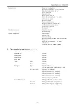
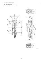
Page 14: ... 12 4 Dimensions T217591 021 0E Specification of CR 200Rf ...

Page 15: ... of KATO may obtain and utilize the recorded data for technical diagnostic purposes or for mobile crane research and development Disclosure of data KATO and agents of KATO will not disclose or supply the data obtained to a third party except in any of the following cases The owner or user of the machine agreed to disclose the data Disclosure is mandated by order of a court of law or other legal au...

Page 16: ... 14 MEMO ...

Page 17: ...3 General operation devices 11 4 Safety signs 35 5 Precautions on getting on and off the machine 49 6 Precautions when filling with fuel 50 7 Air conditioner 52 8 Color monitor 57 9 Radio 71 10 Entry key system 73 11 Starting and stopping the engine 82 12 Handling the machine in winter and summer 85 13 SCR system 87 14 Clearance sonar system 89 Driving operation 218711 15 Driving safely 95 16 What t...

Page 18: ...peration without outriggers 251 24 Crane operation 258 25 Changing the wire rope number of parts 281 Preoperational checks Pre drive checks 218711 26 Preoperational checks Pre drive checks 285 Index 218711 Index 303 Power Jib Section Separate manual 218721 Inspection and Servicing Section Separate manual 218731 Searcher Hook Section Separate manual 218741 MS 250 Separate manual 218751 ...

Page 19: ...Overhoisting emergency switch 214 2 Working lamp switch 214 7 Boom extension retraction emergency switch 214 3 Slewing warning lamp switch 214 8 Seat bypass switch 215 4 Winch lighting switch 215 9 Loudspeaker system optional 20 5 Slewing free lock switch 214 10 Combustion type air heater optional 25 ...

Page 20: ...ch 144 7 ACS emergency switch 212 19 Rear steering lock release switch 146 8 Accessory socket 23 20 Starter switch 22 9 Color monitor 57 21 Air conditioner 52 10 PTO switch 211 22 Radio 71 11 Rear view camera mode switch optional 59 23 Clearance sonar system indicator 91 12 Power window switch 22 Right console 1 Hook displacement display setting buttons Auxiliary hook 218 5 Auxiliary winch high sp...

Page 21: ...34 4 Rear steering lock release confirmation indicator lamp 130 15 Exhaust temperature warning lamp 130 5 Hydraulic oil warning lamp 129 16 SCR system cleaning indicator lamp manual cleaning switch 136 6 PTO indicator lamp 130 17 Idling level switch 136 7 Outrigger operation OK indicator lamp 128 18 Way side lamp switch 131 8 Power steering pressure warning lamp 130 19 Brake lock switch 135 9 Worki...

Page 22: ...ance alarm setting screen display switch 140 8 Display of battery voltage 132 3 Initial screen display switch 131 9 SCR cleaning cancel switch 133 4 Level gauge confirmation screen switch 260 10 Display of hydraulic oil temperature 132 5 Brightness adjustment mode switch 140 11 Display of torque converter oil temperature 132 6 Select switch for display screen of fuel consumption during crane operat...

Page 23: ...ion switch self reset type 239 2 All outrigger operation switch 239 7 Horizontal vertical selection switch 239 3 Right front outrigger operation switch 239 8 Left rear outrigger operation switch 239 4 Outrigger control panel lamp switch 222 9 Left front outrigger operation switch 239 5 Outrigger emergency switch 222 ...

Page 24: ... 22 MEMO ...

Page 25: ...Precautions on getting on and off the machine 49 6 Precautions when filling with fuel 50 7 Air conditioner 52 7 1 Function of each switch 52 7 2 Temperature setting values and corresponding display 53 7 3 Air outlet setting values and corresponding display 53 7 4 Fan speed setting values and corresponding display 54 7 5 Heating mode display 54 7 6 Display when errors are detected 56 8 Color monitor ...

Page 26: ...7 Characteristics of the tags 81 11 Starting and stopping the engine 82 11 1 Starting the engine 82 11 2 Stopping and parking 84 12 Handling the machine in winter and summer 85 12 1 Handling in winter 85 12 2 Handling in summer 86 13 SCR system 87 14 Clearance sonar system 89 14 1 Description 89 14 2 Precautions Be sure to read this section 89 14 3 System configuration 91 14 4 How to use the system...

Page 27: ...Part names and terms 1 Part names and terms 1 1 Part names and terms 541A 0019 0E 1 1 Part names 541A 0020 0E 1 1 1 Exterior 541A 0268 0E ...

Page 28: ...ment due to the load lifted load weight working radius Outriggers Used to level the machine They extend sideways from four locations on the carrier body and support the machine Load lifting off the ground Lifting the load and pausing briefly when the load is slightly clear off the ground Front and rear left and right The boom top with the machine in the driving configuration is defined as the front R...

Page 29: ... except the lifting capacity for jib use The value on the lifting capacity chart indicates the actual working radius under load including deflection of the boom Hoisting direction The direction of the boom top in the driving configuration is defined as the front and the right left and rear are determined accordingly The actual lifting capacity may vary depending on the hoisting direction even if all ...

Page 30: ... 4 MEMO ...

Page 31: ... the safety regulations and laws of the country where the crane is used 2 1 General precautions 0099 0008 0E 2 1 1 General precautions 0099 0226 0E 1 Wear protective clothing and equipment When operating the crane do not wear clothing which might catch on control levers or mechanical parts Wear a helmet protective goggles safety boots a mask gloves etc as necessary 2 Do not work when you are unwel...

Page 32: ... or use fire near fuel oil Long Life Coolant or battery there is the risk that it could ignite Extinguish all fires and potential sources of ignition when handling these flammable materials and do not allow them nearby Switch off the engine before refueling and check that there are no fires or potential sources of ignition nearby After refueling or inspections fasten all fuel and oil caps securely an...

Page 33: ...erator s seat before starting the engine so that you can reach all control levers and pedal comfortably with your back resting on the seat back and fasten the seatbelt 10 Only the operator may be in the cab Before and during work nobody other than the operator may sit in the operator s seat or climb onto the crane Passengers may collide with obstructions or be thrown off the crane or they may caus...

Page 34: ...or fuel Check that paper scraps or other flammable materials are not scattered about or piled up near the engine 14 Start the engine from the operator s seat Always start the engine while seated in the operator s seat If you are not in the operator s seat when you start the engine you will not know the positions of the control levers or the condition of the monitor display so this is a dangerous p...

Page 35: ...re you start the engine Before you board the crane check that there is nobody nearby When you are about to start the engine sound the horn to warn people nearby 17 Before you start the engine check that all the levers pedals and switches are in their neutral or OFF positions ...

Page 36: ... 10 MEMO ...

Page 37: ... 11 3 General operation devices General operation devices 3 General operation devices 061A 0003 0E 1 Inside the cab ...

Page 38: ... 12 3 General operation devices 2 Outside the cab ...

Page 39: ...t your hands or head out through the door or windows while driving or operating the crane If you open the door open it all the way back until the door open lock is engaged If you operate the crane with the door fully opened make sure that the door open lock is engaged If you operate the crane with the lock not engaged the door could slam shut dangerously during slewing operation While driving on a...

Page 40: ...ss the knob while adjusting for height 2 Reclining lever Sit in the seat and adjust the reclining angle of the seat back Pull the reclining lever and adjust using your body weight until the angle is right If it is required to fold down the seatback forward while you are working with the crane be sure to bring the armrest in the raised position beforehand Otherwise the armrest could hit against the...

Page 41: ...s pivoting about the front of the seat 4 Slide lever You can adjust the position of the seat forward or backward Sit in the seat and adjust the seat position matching the steering wheel accelerator pedal and brake pedal 5 Weight adjustment dial Turn the dial to adjust the suspension firmness using the weight markings located to the side of the dial as a guideline between 50kg and 120kg 6 Armrest To...

Page 42: ... levers are disabled Be sure to sit properly in the seat when operating the crane The switch may not detect the operator if the operator is not sitting in the proper position If the switch fails to detect the operator when the operator is properly seated or the operator takes a forward inclining posture during crane operation use the seat bypass switch T218351 012 0E 3 Seatbelt Always fasten the s...

Page 43: ...the fastening pulling the belt end through the tang 2 How to remove and tow the seatbelt Press the removal button on the buckle once and remove the tang from the buckle 4 Interior lamp ON DOOR OFF The lamp is switched on regardless of the door opening closing The lamp is linked to the door to light when the door is open The lamp is switched off regardless of the door opening closing ...

Page 44: ... do not put your hands through the open window Your hands could be caught in the derrick cylinder or boom T218351 060 0E 6 Sunshade Grip the knob in the center area to pull out or stow the shade The shade can be stopped at any position Operate the sunshade by gripping the knob in the front center area to pull out or stow the shade Operating the sunshade by gripping any other area could cause it to...

Page 45: ...nside the fuse box If a fuse blows investigate the cause with the starter switch in the OFF position After checking that there are no short circuits in the wiring replace the blown fuse with a spare fuse of the same capacity Never use a fuse with a higher capacity than specified or a wire etc 8230 0025 0E 8 Holders for the lifting capacity chart and instruction manual ...

Page 46: ... 20 3 General operation devices 9 Keys 10 Hanger hook 11 Loudspeaker system optional For more information see the attached instruction manual ...

Page 47: ...ever the door is open Switch it OFF if the crane will not be used for a long period or if nobody gets into or out of the cab at night or in darkness If the door is left open for a long time in the half door position the battery will run down 541A 0030 1E 13 Lunch table optional Keep the lunch table stowed while you are driving or operating the crane ...

Page 48: ...E 2 Starter switch OFF In this position the key may be inserted and withdrawn and the power to the radio etc is cut off If you leave the operator s seat take the key out When you turn the key to OFF to stop the engine it takes 4 5 seconds for the indicator lamps to go out even if the engine has stopped This is for circuit protection and is quite normal 541A 0033 2E ACC The engine stops in this posi...

Page 49: ...turn to the ON position automatically The engine starts only when the shift lever is in the N position The machine is equipped with an entry key system that prevents starting the engine unless the preregistered startup tag black is touched against the entry key system and properly recognized except if the entry key system is not registered For more details refer to Entry key system T218111 135 0E ...

Page 50: ...s that require up to 1 2 A of power per port or up to a total of 2 4 A via both ports Make sure the device is compatible before using the ports such as by checking the device instruction manual KATO will not provide warranty repairs for malfunctions failures to devices used or for damage or data loss Do not insert metal or other objects into the ports Also make sure no water or other liquids get i...

Page 51: ... if the wiper switch is OFF in the neutral position the wiper will work for a few strokes every time the washer switch is pressed to use the sprayed fluid to clean the roof window Do not press the washer switch for more than 15 seconds continuously at one time If you keep pressing the switch for a long time the pump could break down Do not press the switch if the washer tank is empty as this could ...

Page 52: ...door closed 2 Washer tank The tank which is located at the left front of the slewing table has a capacity of 2 2L Use automobile cleaning fluid NOTE This tank is used for both the front and roof wipers Beware of freezing washer fluid at night or in winter If you press the washer switch while the washer fluid is frozen you will damage the pump Always check that there is enough fluid in the washer tank ...

Page 53: ...these indicator lamps indicate the same information as the engine trouble warning lamp on the cluster meter panel as shown below Diagnostic indicator lamp Engine trouble warning lamp Buzzer Malfunction that prevents driving or dangerous to driving Red lamp lights Red lamp lights or flashes Rapid intervals every 0 5 seconds Malfunction that permits driving only to obtain servicing or other emergency...

Page 54: ...me very hot immediately after stopping the engine Therefore make sure the engine has cooled down sufficiently before opening the engine cover to inspect the engine Leaving the engine cover open can be dangerous as it may close unexpectedly from wind gusts or other causes When opening the engine cover open it completely without stopping part way Do not open the engine cover in strong winds T218151 00...

Page 55: ... dangerous flammable items in the toolbox They could cause a fire Be sure the toolbox is closed and locked during driving Leaving the lid open during driving could cause items stored in the toolbox to fall out and damage the toolbox or machine or cause a traffic disturbance 881A 0039 2E 7 Left forward view camera color ...

Page 56: ... the fuse box If a fuse blows investigate the cause with the starter switch in the OFF position After checking that there are no short circuits in the wiring replace the blown fuse with a spare fuse of the same capacity Never use a fuse with a higher capacity than specified or a wire etc 8230 0025 0E 9 Radio aerial Raise the aerial to use the radio ...

Page 57: ...e operator cab If the ratios reach 100 a red lamp lights and the crane automatically stops Make sure the green lamp is always lit on the ACS outside indicator during crane operations The yellow and red lamps indicate the probability of an accident occurring is high T218351 014 0E 11 External alarm system The external alarm system emits the alarm sound to give a warning to the outside When the red ...

Page 58: ...neral operation devices 13 Way side lamp optional The lamp is lit when the way side lamp switch is pressed with the lighting switch in the position of or 14 Side marker lamps optional 15 Heated mirrors optional ...

Page 59: ...ly from the storage box T217051 039 0E 17 Outrigger plate stowage brackets optional Make sure the outrigger plates are stowed securely with stoppers installed and locked in the correct positions to prevent the plates from falling out Driving without the stoppers installed properly could cause the outrigger plates to fall out damage the machine from being thrown from the brackets or cause other tra...

Page 60: ... 34 MEMO ...

Page 61: ...o read If a safety sign is dirty use water or a neutral cleaner to remove the dirt Do not use gasoline or organic solvents If it is not possible to remove the dirt or if a safety sign is damaged or peeling replace the safety sign with new Refer to the parts list on the crane and order a new sign from your authorised KATO dealer to replace the safety sign When you replace a safety sign always check...

Page 62: ... 36 WARNING 4 Safety signs 6 Content Notes for the lifting capacity chart Location Inside the cab Part No 44A 75106001 6 Content Notes for crane operation Location Inside the cab Part No 44A 75106001 ...

Page 63: ...the cab Part No 44A 75117000 58 Content Check list for outrigger setting Location Inside the cab Part No 611 75116001 59 Meaning Always keep the instruction manuals in the cab and check their contents repeatedly Be sure to read the instruction manuals carefully and familiarize yourself with the contents before operating the crane If you cannot understand how to manipulate or deal with the crane co...

Page 64: ...with the outriggers extended Location Inside the cab Part No 371 75118001 62 Content Precaution when going downhill and overrunning Location Inside the cab Part No 371 75119001 67 Content How to adjust the minimum boom length indicator Location Inside the cab Part No 421 74839000 69 Content Warning when handling the accumulator Location Inside the right engine compartment Part No 707 75109001 ...

Page 65: ...t No 001 81302010 82 Meaning Do not allow anybody even other site workers to enter the rear slewing radius Location Left and right sides on the rear of the slewing upper structure Part No 001 81312015 84 Content Exhaust gas hazard Location Inside the cab Part No 899 81228582 85 Content Precautions when stowing the hooks Location Inside the cab Part No 899 81428612 ...

Page 66: ...572 94 Content Precautions for the bridging device Location Bridging device door Part No 44A 75124000 98 Meaning Never bring any flame or source of ignition near the fuel tank Location Top surface of the heater fuel filler port deck when the optional part is equipped Part No 001 81332005 99 Content Add diesel fuel only in the fuel tank Location Top surface of the heater fuel filler port deck when the...

Page 67: ... 41 4 Safety signs WARNING Safety signs 2 Boom and jib 1 Content How to connect the connector for overhoisting detector Location Right side of the boom top Part No 44A 75801001 ...

Page 68: ...ector for overhoisting detector Location Right side of the jib Part No 581 75602000 21 Meaning Do not allow anybody even other site workers to pass under the suspended load Location Underside of the boom base Part No 821 75022000 22 Content Note for the rope retaining pin Location Left side of the auxiliary hook stowage bracket Part No 899 81320802 ...

Page 69: ... detach the boom guard Location Front of the boom guard Part No 899 81422512 86 Content Note when lowering the boom Location Inside the cab Part No 899 81430492 87 Meaning Note for the boom angle when swinging out or stowing the jib Location Inside the cab Part No 899 81421572 ...

Page 70: ...rt No 899 81421082 6 Content Check the DEF AdBlue level Location Near the fuel filler port Part No 44A 75506000 15 Meaning Do not touch the engine its surrounding the fan belt or the rotating parts of the fan while the engine is running or immediately after it has stopped Location Inside the engine cover Part No 001 81332019 ...

Page 71: ...e to cool Location Inside the engine cover Part No 001 81332002 18 Meaning Beware of high temperature If touched carelessly you will get burned or serious injury Location Sides of the DOC cover and the SCR cover and inside of the engine cover Part No 44A 75518000 21 Content Prohibition of high pressure cleaning Location Front sides of the relay box and the battery relay box and top surface of the ...

Page 72: ...n handling the battery Location Side of the batteries Part No 707 75122001 44 Content Prohibition of high pressure cleaning Location Sides of the DOC cover and the SCR cover Part No 44A 75544000 45 Meaning Beware of high temperature Location Left rear of the machine body Part No 001 81322003 48 Content Wheel chocks Location Right side of the machine body Part No 899 81428082 ...

Page 73: ...eaning Always keep the instruction manuals in the cab and check their contents repeatedly Be sure to read the instruction manuals carefully and familiarize yourself with the contents before handling the machine If you cannot understand how to manipulate or deal with the machine contact your authorised KATO dealer Location Inside the cover of the outrigger control panel Part No 001 81332001 101 Con...

Page 74: ... 48 MEMO ...

Page 75: ...ree points of support at all times on the hand grips and steps Do not use the control levers to hold on to Jumping onto or off the machine can cause injury It is also dangerous to get on or off the machine while it is in motion The hand grips steps etc are slippery when they have mud or oil on them so wipe them clean before you get on or off the machine If attachment bolts of hand grips or steps are ...

Page 76: ...and a major accident could result Stop the engine and turn the starter switch to OFF before you start filling Do not use any type of water remover Stop the engine in a well ventilated place and check that there is nobody inside before you start filling Do not allow any fire or source of ignition nearby Take care not to spill fuel on hot areas If any fuel spills wipe it up immediately As soon as you fi...

Page 77: ...l engine fuel should satisfy the following criteria Does not contain even fine dust Has adequate viscosity Has a high cetane number Has good low temperature flowability Has low sulfur content 15ppm or less Has low carbon residue Use standard automotive diesel fuels JIS K 2204 EN590 ASTM D975 GOST R52368 GB252 that meet the requirements above Never add a water remover additive or non diesel fuel Doin...

Page 78: ...pressor thermostat operation ON OFF However operating actions vary depending on the temperature setting Cooling mode A C remains ON A C switch is disabled Heating mode A C can be switched ON OFF using the A C switch Intermediate settings A C remains OFF A C switch is disabled Fan speed UP arrow switch Fan speed DOWN arrow switch These change the fan speed setting Temperature setting UP arrow switc...

Page 79: ...towards COOL The temperature cannot be decreased when COOL MAX is displayed 7 3 Air outlet setting values and corresponding display T217921 017 0E 1 The indicator displayed for each air outlet setting is shown below 2 How to change the air outlet mode With each recognized press of the air outlet mode switch the air outlet mode changes in the sequence VENT2 FOOT DEF FOOT VENT1 VENT2 and so on It on...

Page 80: ...larly with each recognized press of the fan speed DOWN arrow switch the fan speed decreases by one level in the sequence Hi M4 M3 M2 M1 Lo and so on The fan speed cannot be decreased when Lo is displayed 7 5 Heating mode display T217921 019 0E 1 Full display An F indicator is displayed on the seven segment display when maximum electromagnetic proportional valve control current is flowing 2 Startup ...

Page 81: ... remains fixed at Lo for three minutes During that period the fan indicator and Lo speed bar indicator flash and the fan speed bar indicators other than for Lo speed the prescribed value are lit 3 High oil temperature display If the oil temperature is too high for operating in the heating mode an E indicator on the seven segment display and fan indicator flash ...

Page 82: ... 56 7 Air conditioner 7 6 Display when errors are detected T217921 020 0E ...

Page 83: ...lor monitor 8 Color monitor 8 Color monitor T217051 069 1E 8 1 Part names T218351 017 0E 1 Color monitor Remote control Never operate the monitor while driving T217921 106 0E 2 Left forward view camera color ...

Page 84: ... image automatically switches to the rear view camera image whenever the shift lever is shifted to the R position regardless of the camera mode button status Shifting the shift lever to any gear position restores the image displayed before shifting to the R position T217161 067 0E 4 Winch camera color Winch light ...

Page 85: ...ture rear view camera and the wireless rear view camera cannot be displayed on the split screen Orient the antenna for the wireless rear view camera in the same direction as the antenna on the receiver located inside the cab Not orientating both antennas in the same direction could affect wireless signal reception T217921 114 0E Precautions for models equipped with the rear view camera The screen i...

Page 86: ...rned off 2 VOL Volume control button volume control Volume can be controlled by holding down the button on the monitor or by pressing the VOL button Only the camera 1 REAR and the external input AUX allow sound input 3 Mute button Mute When the mute button on the remote control is pressed sound is vanished When the mute button is pressed again vanish is cancelled Mute is also cancelled by operating...

Page 87: ...onitor or any split screen button on the remote control is pressed splitting method for split screen can be selected 6 Input image switching 1 Camera input switching When the button on the remote control is pressed camera input is switched If the button is used camera input is switched in the reverse order If the buttons on the monitor are used to switch camera input press the button after switchi...

Page 88: ...reen setting When the MENU button on the monitor or the SETUP button on the remote control is pressed under a split screen status the split screen setting screen appears Example of setting of split screen NOTE In case of split screen by any other method the setting method is the same Example of setting of triple split screen NOTE In case of triple split screen by any other method the setting metho...

Page 89: ... trigger image switching setting When a signal is input the corresponding camera image is displayed on a full screen When the signal is cancelled the previous screen is restored If the signal inputs 2 and 3 are entered at the same time the image by the camera 2 is displayed on a full screen Camera input can be switched even while the image of the signal inputs of 1 to 4 are displayed To switch cam...

Page 90: ...rigger image switching setting The following operation methods to are applicable to the case where the signal input 1 reverse gear is connected to the camera 1 the signal input 2 left turn signal to the camera 2 the signal input 3 right turn signal to the camera 3 and the signal input 4 others to the camera 4 respectively When a signal is input the corresponding camera image is displayed on a full...

Page 91: ...he signal input 2 or 3 is entered the images of the camera 2 or 3 and camera 1 are displayed on the split screen irrespective of the previous screen When the signal input 1 reverse gear is entered the image by the camera 1 is displayed on the full screen To display it on the split screen press buttons on the monitor or on the remote control While the hazard lamp is in use the right and left turn s...

Page 92: ...standby status the power of the monitor is turned on and the camera image is displayed When the input signal is cancelled the power of the monitor is turned off and STAND BY standby status is recovered The priority order of signal input is as follows Signal input 1 Signal input 2 3 Signal input 2 Signal input 3 Signal input 4 T217051 070 0E ...

Page 93: ...utton on the monitor or the SETUP button on the remote control is pressed three times PICTURE SETUP menu appears Press the MODE button on the monitor or button on the remote control three times to move to the item you want to change and then press button on the monitor or button on the remote control for adjustment 3 Language displayed on the screen Japanese English The factory default language is...

Page 94: ...creen for audio output When the MODE button on the monitor or button on the remote control is pressed the speaker icon moves to each screen 6 Setting screen display When the MENU button on the monitor is held down or the RECALL button on the remote control is pressed the setting screen appears 7 Setting of camera input image Normal mirror When the MENU button on the monitor or the SETUP button on ...

Page 95: ...t marker display position If the CCD camera to be connected is not a product made by Clarion Co Ltd do not set the marker for use T217481 011 0E The marker does not guarantee safety in the actual positions in relation to the bumper position vehicle model vehicle rearward distance T217051 072 0E 9 MARKER SELECT Setting of marker pattern 1 Press the MENU button on the monitor or the SETUP button on ...

Page 96: ...ton on the monitor or button on the remote control to select H V H adjusts horizontal movement and V adjusts vertical movement 3 Press button on the monitor or button on the remote control to switch the market pattern H 10 to 10 V 12 to 12 Default value H 0 V 0 4 The setting screen disappears after 10 seconds and setting is completed If no button is operated the setting screen disappears even in t...

Page 97: ...s the sound balance bass and treble 8 LCD display Displays the frequency clock etc 16EE 0111 1E 9 2 LCD display T218351 061 0E Name Function 1 Segment display large Displays the band name frequency clock and other alphanumeric information 2 Segment display small Displays frequency during FM 50 kHz step mode 3 ST indicator Illuminates to indicate stereo signal reception when FM1 or FM2 band is sele...

Page 98: ...Short press Switches between display modes frequency clock frequency etc Switches adjustment parameter hours minutes enter Long press Switches to clock adjustment mode only if clock is displayed Sound adjustment PWR Short press Switches power OFF Long press AM FM Short press Switches between bands FM1 FM2 AM FM1 etc Long press VOL VOL Short press Adjusts volume 1 step up or down Long press Adjusts...

Page 99: ... in a location exposed to high temperature or humidity levels Do not leave tags immersed in water or oil for long periods Do not store or leave tags near devices that generate a strong magnetic field T218111 137 0E 10 1 System components T218111 165 0E 1 Tag reader 2 Indicator 3 Startup tag black 4 Registration tag red The following tags are provided with each machine Tag type Color and shape Appli...

Page 100: ...registration tag contact an authorised KATO dealer T217201 015 0E 1 To register a startup tag touch the registration tag against the tag reader area When the registration tag touches the tag reader an alarm sounds once and the reader illuminates purple If the registration tag is separated from the reader before the starter switch is turned to the ON position the registration mode is canceled the r...

Page 101: ...artup tag away from the reader turn the starter switch to the OFF position When the starter switch is turned to the OFF position the indicator will change from purple to blue illumination The registration mode is not canceled until the starter switch is turned to the OFF position so be sure to turn the starter switch to the OFF position when finished registering tags T218111 140 0E 5 The number of ...

Page 102: ...g against the reader will cause an error T218111 141 0E 2 Unlocking the entry key system When the entry key system is unlocked the starter switch can be turned to the ON or START position 3 Locking the entry key system The entry key system is locked automatically five minutes after turning the key to the OFF position The indicator changes from steady blue illumination to red flashing NOTE Before th...

Page 103: ...nd the reader illuminates purple If the registration tag is separated from the reader before the starter switch is turned to the ON position the registration mode is canceled the reader light switches OFF If that occurs start over from the beginning T218111 142 0E 2 Keeping the registration tag in contact with the reader turn the starter switch to the ON position When the starter switch is turned ...

Page 104: ...ouched against the reader the tag can no longer be used to unlock the entry key system T218111 018 0E 2 To unregister all registered startup tags touch the registration tag against the reader If all startup tags are unregistered the entry key system will switch OFF so that the engine can be started without unlocking the entry key system If a startup tag is lost it is recommended that all registere...

Page 105: ...When the starter switch is turned to the OFF position the tag reader will change from purple to the following state The registration mode is not canceled until the starter switch is turned to the OFF position so be sure to turn the starter switch to the OFF position when finished registering tags The entry key system switches OFF if there are no startup tags ...

Page 106: ...it can be canceled by touching the startup tag to the reader 10 6 Tag reader specifications T218351 067 0E Tag reader Status Example of action Flashing red Engine startup is locked entry key system is ON Starter switch is turned OFF when engine startup is locked Lit blue Unlocked Authentication process is performed normally when engine startup is locked Lit red Warning Starter switch is turned ON b...

Page 107: ...er of tags can be increased by purchasing separately 2 Case 2 Where a startup tag is used to start up plural machines If plural machines are owned a startup tag can be used to start up all of them 2 Registration tag The registration tag has one to one correspondence with the machine so it cannot be used for registration of any other machines Registration operation is enabled only when the registra...

Page 108: ...for approximately 3 seconds All warning lamps will light when the cluster meter panel is activated If no problem is detected all warning lamps will go out If all warning lamps continue to light or all warning lamps do not light stop the engine start procedure and contact your authorised KATO dealer 121A 0077 2E 5 Starting the engine 1 In normal Turn the starter switch to the START position to star...

Page 109: ...oing through the after starting tests Raising the engine speed without doing warm up running for the engine and torque converter could cause a seizure fast wear damage etc due to poor lubrication from high oil viscosity Properly perform warm up running and confirm that the needle of the engine water temperature gauge is above point C then start to drive or set the PTO switch to the ON position 541A...

Page 110: ... and further seizure in the turbocharger bearing because the supply of lubricating oil to the turbocharger stops 541A 0061 0E 3 Turn the starter switch to the ACC position to stop the engine Once the engine has completely stopped turn the starter switch to the OFF position and take the key out NOTE If the machine is going to the left parked for a long time the area of the tire in contact with the ...

Page 111: ...ommended fuel will reduce performance and could cause a major accident Such problems are not subject to guarantee 541A 0065 1E 2 Engine oil Use an engine oil recommended by KATO or specified by Cummins Cummins Premium Blue Using an oil other than the type recommended by KATO or specified by Cummins could cause engine malfunction failure Engine oil softens lower viscosity at higher temperatures and b...

Page 112: ... 5 Batteries Normally battery electrolyte does not freeze in cold weather but if the battery charge is low some freezing is possible A battery which has frozen is permanently unusable so take precautions to maintain the battery temperature 12 2 Handling in summer 541A 0070 2E Overheating can easily occur in summer so pay attention to the following points 1 Cleaning and inspection of the cooling sy...

Page 113: ...accordance with ISO 22241 1 Do not use any DEF other than the brand specified Do not dilute the DEF or add any additives Doing so could not only result in worse gas emissions but also could cause the machine to fail 2 How to store the DEF Store the DEF in a sealed container kept in a well ventilated location away from direct sunlight The DEF freezes at 11 C Expansion caused by freezing could damage...

Page 114: ... a well ventilated location Once the DEF has been removed from the DEF tank its purity cannot be guaranteed Do not pour it back into the DEF tank If any DEF splashes onto the machinery then wipe it up immediately If left unremoved the urea components could crystallize making it difficult to remove If the cap is difficult to tighten due to crystallized urea around the filler port of the DEF tank remove ...

Page 115: ... reaction speed of the clearance sonar system Therefore be sure to visually confirm the safety around the machine before moving it forward or backward The obstacle detection range could be shorter or obstacles not detectable depending to the obstacle type obstacle shape or surrounding conditions Therefore be sure to visually confirm safety in the surrounding area before operating the machine Do not ...

Page 116: ... below the sensor Obstacle sensors may suddenly stop detecting already detected narrow pilings or objects shorter than the sensor height The obstacle sensor surface is painted If the paint is scraped off such as when removing mud with a sharp tool it could significantly reduce the performance of the obstacle sensor Do not apply any stickers or paint to the top of obstacle sensors Doing so could caus...

Page 117: ...r system 14 Clearance sonar system 14 3 System configuration T218301 018 0E The clearance sonar system includes the following components 1 Ultrasonic obstacle sensors Four sensors are installed on the machine 2 Indicators ...

Page 118: ...ll resume sounding The alarm also sounds when the machine is started up If the starter switch is turned to OFF and then back to ON while the alarm cancel switch is held down then the alarm is uncanceled and the alarm will resume sounding 3 Left front sensor lamp This lamp flashes or lights when the left front sensor detects an obstacle 4 Left front wheel sensor lamp This lamp flashes or lights when ...

Page 119: ...elow Alarm level Alarm lamp Distance detected Left front Left front wheel Rear Left rear corner Level 1 Slow flashing 1 0 0 8m 0 8 0 7m 1 0 0 8m 0 8 0 7m Level 2 Fast flashing 0 8 0 6m 0 7 0 5m 0 8 0 6m 0 7 0 5m Level 3 Lit 0 6m or less 0 5m or less 0 6 m or less 0 5m or less T218351 076 0E NOTE The distances indicated above are provided as a general guideline and do not guarantee the actual distanc...

Page 120: ... 94 MEMO ...

Page 121: ...mission system 105 16 4 Dealing with breakdowns 107 17 Drive operation devices 110 17 1 Cluster meter panel 113 17 2 Information display 128 17 3 Front and side panel switches 143 17 4 Accelerator and brake pedals 150 17 5 Steering column 151 17 6 Lower control switch panel 155 18 Driving the machine 158 18 1 Preparations for driving on the roads 158 18 2 General driving 161 18 3 Specialized drivi...

Page 122: ...and equipment 2 Set the PTO switch to the OFF position and return the machine to the driving position before driving on the roads Never operate the crane in any way when driving on the roads 3 Precaution for rear steering Always keep the rear steering locked and use only front two wheel steering when driving on the roads If the rear steering lock is released the rear steering lock release lamp wil...

Page 123: ... can disable the brakes dangerously 7 Sudden acceleration braking and cornering should be avoided unless required in an emergency These maneuvers cause rapid wear of the tires and brakes 8 Pay attention to road surface conditions Drive slowly and cautiously for maximum safety on snow covered or icy roads irregular road surfaces inclined ground roads sloping up and down etc Check the road surface b...

Page 124: ...particular check the height and width of the opening in advance when driving under power cables or bridges 11 Allow adequate distance for stopping Allow adequate distance for stopping so that the front of the machine i e the boom top does not cross over stop lines 12 Steering control This machine is equipped with fully hydraulic power steering This makes the steering wheel lighter to turn but mean...

Page 125: ...any position other than N while the parking brake is applied the warning buzzer will sound 3 When stopping temporarily at crossings or traffic lights etc use the parking brake and return the shift lever to the N neutral position If you use the foot brake while the machine is at rest the brake fluid will heat up Try to release the foot brake as much as possible to allow the brake fluid to cool 4 While ...

Page 126: ...ng so could cause brake fade or vapor lock phenomena due to increased brake temperature which in turn could cause an accident Brake fade Brake fade is a phenomenon where the brake shoe surface melts due to heat which reduces braking forces due to the lower friction forces between the brake shoe and brake drum 7 Braking on a downhill Be particularly careful braking when going downhill Excessive bra...

Page 127: ...nnot be modified because exhaust gas aftertreatment system failure or engine stop may be caused 2 Use low sulfur diesel fuel with sulfur content of 15 ppm or less If not engine stop may be caused Do not use any type of water remover 3 Exhaust gases become significantly hotter during SCR system cleaning than conventional machines Therefore be careful not to park near flammable substances Also be care...

Page 128: ...e it adversely affects the SCR system and engine 6 Use low ash engine oil E9 standard Use an engine oil recommended by KATO or specified by Cummins Cummins Premium Blue Using an oil other than the type recommended by KATO or specified by Cummins could cause engine malfunction failure Engine oil softens lower viscosity at higher temperatures and becomes thicker higher viscosity at lower temperatures ...

Page 129: ... 102 MEMO ...

Page 130: ...the methods below to warn other drivers of the breakdown 1 Breakdown warning methods Emergency signal equipment emergency signal lights Red flag or red lamp Stop sign Tie a handkerchief etc in a prominent place on the back of the machine 3 You must place blocks etc as chocks in front of the wheels 4 Investigate the cause of the breakdown and repair it if you are able to do so yourself While doing s...

Page 131: ...1 108 0E 1 If the power steering pressure warning lamp on the switch panel lights while the machine is in motion leave the starter switch ON and steer gently while checking the safety of your surroundings to roll to a stop in a safe place NOTE If you move the machine backward during evasive maneuvers the emergency power steering will be disabled Be sure to move the machine forward only 2 After bri...

Page 132: ...the cluster meter panel in the cab will light to alert the driver Depending on the cause of the malfunction the automatic shift control may not function in which case it will be impossible to go on driving In this case use the system switch AT M emergency switch which is located in the lower control box on the left side of the lower structure This will allow you to continue driving using manual tr...

Page 133: ...y side to continue to drive unavoidably normal driving with the shift lever in the D range automatic gear change is impossible so use manual gear change to continue driving You must choose the optimum gear for the speed range you are driving in at any time Manual shift position guidelines for machine speeds Position Speed range 1 0 18km h 2 18 27km h 3 27 39km h D 39 55km h R 0 27km h T218351 023 ...

Page 134: ...r authorised KATO dealer as soon as possible If you make a mistake in connecting the booster cables the following problems could result so work with care Serial connection with an assisting machine using 24V Voltage will exceed 24V which will burn out the starter motor and could cause a fire 541A 0080 2E 16 4 2 Overheating 541A 0276 2E 1 Overheating while driving 1 Stop the machine in a safe place ...

Page 135: ...open it 541A 0082 1E 2 Overheating during crane operation 1 Stop using the crane Do the same procedure as 1 Overheating while driving 2 5 above 16 4 3 Towing T217051 081 0E Investigate the cause of the breakdown If you consider it impossible to repair on site have the machine towed away for repairs In this case follow the procedure below Contact your authorised KATO dealer to have it make the nece...

Page 136: ... of the towing machine to that of the broken down machine The supply of compressed air to the broken down machine can be provided through the coupler on the underside of the compressed air tank Then take the same actions as 4 8 described in 1 above If the cause of the breakdown is not the engine and the engine may be used without causing problems If you do not provide the broken down machine with ...

Page 137: ...ive operation devices 17 Drive operation devices 061A 0012 0E Familiarize yourself with the names and operation methods of the devices such as levers meters switches etc before you start to drive 1 Inside the cab ...

Page 138: ... 111 17 Drive operation devices Drive operation devices ...

Page 139: ... 112 17 Drive operation devices ...

Page 140: ...ng between km h and km h MPH on the cluster meter panel Press the km h switch or km h MPH switch on the temperature voltage confirmation screen to switch the speedometer indication between km h and km h MPH on the cluster meter panel Switching the speedometer indication between km h and km h MPH also switches indications for possible driving distance and used amount of fuel on temperature voltage c...

Page 141: ... cumulative distance driven by the machine Displays up to 6 digits in 1 km increments 2 Trip meter A B Displays the distance driven since the last time it was reset Displays up to 5 digits in 0 1 km increments 4 Odometer trip meter switch 1 Switch between odometer and trip meter A and B modes by briefly pressing the key ON OFF switch and the trip A or B switch 2 When the trip meter is displayed th...

Page 142: ...ngine is running If the air pressure climbs above 9 stop the engine immediately and contact your authorised KATO dealer 9 DEF level meter Indicates how much DEF is remaining F indicates full and E indicates a small amount is remaining The warning message is displayed with the flashing or lit warning lamp on the cluster meter panel if the DEF level drops below 10 Therefore be sure to replenish the D...

Page 143: ...perating status or SCR system A pop up window for error occurrence display also appears on the information display Immediately stop the machine in a safe location and contact your authorised KATO dealer 7 Radiator coolant level warning lamp This lamp lights when the level of coolant in the radiator is too low Check the volume of coolant 8 AT M automatic transmission malfunction warning lamp This l...

Page 144: ...s intermittently 0 5 seconds intervals If oil temperature is above the rated temperature The warning lamp lights and the buzzer sounds intermittently 1 second intervals If there is a problem with sensors or wiring The warning lamp flashes T217161 016 0E 10 Auxiliary brake indicator lamp This lamp lights when the auxiliary brake lever switch is ON The auxiliary brake is activated when the auxiliary ...

Page 145: ...lockage warning indicator lamp This lamp lights when the air cleaner filter element is blocked If the indicator lamp lights replace the air cleaner filter element T218151 024 0E 15 Overrun warning lamp When driving speed exceeds the rated speed or if the engine speed exceeds the rated revolutions this lamp lights and a slow intermittent warning buzzer sounds If this warning lamp lights you must appl...

Page 146: ...tarted running at slightly higher speed It also flashes when the battery voltage drops below 20V and the warning buzzer sounds Increase engine speed to regain battery voltage If this lamp lights while the machine is in motion it is due to a malfunction of the alternator system Contact your authorised KATO dealer 18 Brake fluid level warning lamp This lamp lights and an intermittent buzzer sounds at ...

Page 147: ...n is performed Rapid flashing 0 5 seconds intervals 521A 0057 0E 21 SCR system warning lamp If the DEF level drops below 10 or a problem with the component in the SCR system or DEF quality is detected a warning is displayed as described below If the machine continues to be operated without taking appropriate actions after the warning is displayed use of the machine engine torque and speed will be r...

Page 148: ...this warning is displayed promptly replenish the specified type of DEF The warning will be canceled once the specified DEF is replenished 2 SCR system error warning This is displayed if a problem is detected with a component in the SCR system If this warning is displayed promptly inspect the system and contact your authorised KATO dealer ...

Page 149: ...lity error the waning is canceled and another warning with a lower warning level than the warning at point B in the figure below is displayed again within 40 minutes after canceling the previous warning then a warning will start again from the point the system was restored from the previous error situation Therefore the warning will restart at points A or A for example where the system was restored...

Page 150: ...s displayed until the final warning is reached A countdown before restricting the engine to minimum output is also output when malfunctions unrelated to the SCR system occur T217921 110 0E 22 Exhaust gas related malfunction warning lamp If a problem with the exhaust system is detected a warning is displayed as described below If the machine continues to be operated without taking appropriate action...

Page 151: ...ion display of the lower structure 1 The driving direction is displayed by an arrow near the tire steering angle display on the cluster meter panel It is displayed as shown in the table below when the slewing angle is 5 degrees or more Range D 1 2 or 3 Range R Range N Driving with rear steering locked Lit Lit Unlit Driving with rear steering released Flashing Flashing Unlit T218351 090 0E 25 Engin...

Page 152: ...the clearance lamp is turned on 29 Message display If a machine error occurs a warning message is displayed in addition to a lit or flashing warning lamp A maintenance message can be displayed whenever it is time to replace a lubricant or other consumable All maintenance messages are hidden by default settings To display maintenance messages change the settings in the maintenance alarm setting scr...

Page 153: ... 126 17 Drive operation devices ...

Page 154: ... 127 17 Drive operation devices Drive operation devices ...

Page 155: ...ion lies between the ACS and the communications system this lamp flashes a pop up window for error occurrence display appears and an intermittent buzzer sounds 1 second intervals If this lamp flashes stop the engine immediately and contact your authorised KATO dealer 2 Outrigger operation OK indicator lamp This lamp lights when the PTO switch is ON and the front area switch is ON or when there is an...

Page 156: ...ension operation OK indicator lamp is lit This lamp lights if the shift lever is at the N position the PTO switch is OFF and the front area switch is ON when there is an ACS system error When the suspension operation OK indicator lamp flashes the safety processing is performed against the suspension misoperation etc Try to perform the suspension operation correctly 521A 0058 0E 5 Hydraulic oil warn...

Page 157: ...when the rear steering lock is released by moving the rear steering lock release switch to the release side This lamp flashes while the steering mode is being switched from the lock mode to any other mode NOTE At the same time the rear steering lock release indicator lamp on the cluster meter panel will also light 9 Rear steering central position indicator lamp This lamp lights when the rear steeri...

Page 158: ...osition the misoperation warning buzzer pip pip will sound and the way side lamp will not light T217051 097 0E 2 Temperature voltage confirmation and fuel consumption display screen mode switch How to switch to the temperature voltage confirmation screen Switch to the temperature voltage confirmation screen by pressing the temperature voltage confirmation mode switch on the initial screen It displays ...

Page 159: ...lic oil temperature indicator lamp lights 2 Display of torque converter oil temperature Torque converter temperature When the oil temperature inside the torque converter rises above 120 the torque converter trouble indicator lamp lights and the warning buzzer sounds intermittently 1 second intervals 49 or lower blue From 50 to 119 green 120 or higher red Temperature of 14 or lower is 3 Display of ...

Page 160: ...d cleaning is in the canceled status shown in red and cleaning is not carried out By pressing this switch again the cleaning canceled status is canceled and cleaning is carried out 3 Two four wheel drive switch Use this switch to choose the driven wheels The axles 1 and 2 are driven 1 If the two four wheel drive 4WD switch lights in blue the machine is in two wheel drive mode When you press the sw...

Page 161: ... you attempt to shift while driving at 3km h or more the misoperation warning buzzer pip pip will sound When switching between high and low range at over 3km h the low range indicator lamp will flash rapidly T217051 099 0E 1 When the color of the low range switch is blue the transmission is in high range When you press the switch in this mode the confirmation buzzer pip will sound and the low range ...

Page 162: ...brake lock switch lights in blue the brake lock has disengaged The brake lock must not be used as a substitute for the parking brake The brake lock can only be used while the engine is running and the parking brake is engaged 541A 0100 0E If air pressure inside the compressed air tank drops while the brake lock is engaged the warning buzzer sounds Raise the engine revolutions to increase pressure ...

Page 163: ...engine warm up for example press the up arrow button to increase the engine speed in 100 min 1 increments Press the down arrow button to decrease the engine speed in 100 min 1 decrements 7 SCR system cleaning indicator lamp manual cleaning switch 8 Eco switch When the PTO is OFF When this switch is selected the engine power is decreased and fuel economy is improved during driving ...

Page 164: ...the exhaust temperature Because this involves raising the exhaust temperature be careful of burn injuries or fire ignited from the hot exhaust gas or exhaust system surfaces 3 Manual cleaning If operating load levels are low and automatic cleaning was not performed the operator can initiate cleaning manually The engine speed is increased to about 1000 min 1 during manual cleaning Due to the increa...

Page 165: ...ble use the SCR cleaning cancel switch For more details refer to the instruction manual If the SCR system is cleaned near a painted wall the hot exhaust gases could discolor the wall If the SCR system is cleaned near a hedge the hot exhaust gases could scorch the hedge T218151 031 0E Only clean the SCR system manually in the driving mode Be sure to switch the PTO switch to the OFF position before ...

Page 166: ...reen has not yet been selected 3 Display of possible driving distance As soon as the residual amount of fuel is exhausted 0 is displayed as the possible driving distance 4 Trip A and B reset switches Use these switches to reset trip meter values These switches reset the driving distance used amount of fuel and possible driving distance values for the currently selected trip meter NOTE Trip meter v...

Page 167: ...n be adjusted to five different levels The default daytime brightness level setting is 5 but it can be adjusted to values between 0 and 5 The default nighttime brightness level setting is 3 but it can be adjusted to values between 0 and 5 17 2 6 Maintenance alarm setting screen T218151 150 1E This screen is displayed by pressing the maintenance alarm setting screen display switch in the temperature ...

Page 168: ...ng possible Values higher than the default distance and hours settings cannot be specified The specified maintenance alarm display timing is displayed in the setting value for driving distance before emitting alarm or setting value for alarm time setting fields Specify the timing for replacing lubricants and other consumables in accordance with the Inspection and Servicing Section 4 The current cumul...

Page 169: ...ir cleaner element 1000h Hydraulic oil return filter element 500h Hydraulic oil spin filter cartridge 500h Filter element for torque converter oil ATF 10000km Oil filter element for steering 1000h Hydraulic oil bypass filter element 1000h Brake fluid 10000km Air dryer desiccant and O ring 10000km Torque converter oil ATF 10000km Differential gear oil 10000km Planetary hub gear oil 10000km Tire rotation ...

Page 170: ...s or stows only the selected mirror Adjust the side view mirrors so the left and right sides of the machine can be seen when sitting in the operator s seat with the machine in the driving position Always set the side view mirrors in the driving position extended before driving on the road Do not use the side view mirrors as a hand hold for climbing up or down from the machine Rotating the mirrors ...

Page 171: ...ion unlocked the suspension depending on the crane operation status Do not operate the suspension while the outriggers are extended When the suspension lock is released there is some risk that the axles could drop off 541A 0106 0E Release the suspension lock and switch to the driving mode before driving on roads Driving on roads with the suspension lock cylinders retracted is extremely dangerous Pe...

Page 172: ...eleased operating the suspension control switch towards suspension retraction retracts the suspension cylinders as long as the switch remains depressed 2 Suspension lock Use the suspension control switch to retract the suspension cylinders fully When you release the switch the suspension cylinders will be set to the suspension lock position automatically and the suspension locked indicator lamp wi...

Page 173: ...g position the suspension will be locked at that position Even if you set the PTO switch to the OFF position at this status the suspension lock will not be released At this time the suspension operation OK indicator lamp will flash rapidly Move the suspension control switch to the suspension lock position and then move it to the suspension lock release side to release the suspension lock 541A 0109 ...

Page 174: ...ction in any device related to rear steering or when the rear steering emergency switch is ON the rear steering mode cannot be switched The misoperation warning buzzer pip pip will sound If it is impossible to lock the rear steering automatically operate the rear steering lock release switch again If it is impossible to release the rear steering lock move the machine forward slightly Then try to r...

Page 175: ...and set the mirror heater switch to the ON position the battery will run down Be sure to set the mirror heater switch to ON position while the engine is running T217161 113 0E 17 3 2 Side panel T218151 108 0E 1 Shift lever This lever shifts the transmission gear as follows R To drive the machine in reverse N To start the engine and keep it running in neutral D For normal driving Gear ratio varies ...

Page 176: ...e speed sufficiently the transmit will not shift down to the lower position Also on downhill slopes with speeds 1 2 or 3 selected the transmission will automatically shift up one position when the driving speed exceeds the speed range for the selected gear In this case the effect of engine brake will be lost Take great care to keep the machine s speed within the range of the selected shift position N...

Page 177: ...foot brake for use while the machine is in motion The disk brakes on the front and rear wheels act when the pedal is pressed in proportion to the amount of pedal depression When driving down a long slope use the engine brake and axiliary brake to avoid overusing the foot brake T218151 102 0E If the air pressure in the foot brake circuit falls below the rated pressure 500 900kPa 5 9kgf cm2 the avai...

Page 178: ...again to lock the adjusted position NOTE The ranges of adjustment are as follows Height adjustment 40mm Angle 10 Only adjust the steering wheel position while the machine is at rest Always fasten the lock lever securely after adjusting the angle and height of the steering wheel If the lever is loose the steering wheel could move unpredictably while the machine is in motion and cause an accident 54...

Page 179: ...y wiper action Knob setting position Wiper action OFF Stop INT Intermittent LO Slow HI Fast T217921 098 0E 2 Windscreen washer switch The windscreen washer switch is located on the end of the knob Press it to spray cleaning liquid from inside the windscreen washer tank out through the nozzle After the windscreen washer sprays the wiper will work for a few strokes even if it is not switched on to u...

Page 180: ...e driving speed is at least 10km h NOTE When the auxiliary brake lever switch is set to the ON position the auxiliary brake indicator lamp will light on the cluster meter panel 2 Turn signal and dimmer switch This switch incorporates the following switching functions Turn signal lever switch Lighting switch Dimmer switch 1 Turn signal lever switch Move the lever switch in the direction you are goi...

Page 181: ...mer switch Move the lever forward and backward to work the dimmer switch High beam Move the lever forward with the lighting switch in position to turn the headlamps to high beam The high beam indicator lamp on the cluster meter panel also lights Passing Move the lever toward you in any lighting switch position to turn the headlamps to high beam only for as long as you lift the lever The high beam ...

Page 182: ...tinue driving in D range turn this switch to the emergency position You may now continue driving using manual transmission The shift positions now correspond to fixed gears D is fourth speed 3 is third 2 is second and 1 is first Choose the optimum gear at all times to prevent the engine from over running Persistent over running of the engine could lead to seizure and severe damage NOTE It is impossi...

Page 183: ...to use manual gear change in the low range Manual shift position guidelines for machine speeds high range Position Speed range 1 0 18km h 2 18 27km h 3 27 39km h D 39 55km h R 0 27km h T218351 023 0E When the AT M emergency switch is switched to the emergency side the lockup mechanism is released so engine braking will not function Reduce the driving speed not to overuse the brakes T218151 115 0E ...

Page 184: ...lease or lock status Make sure that the error display disappears then set the desired lock release status 581A 0062 1E When using the rear steering emergency switch the rear steering lock release indicator lamp on the cluster meter panel inside the cab will flash rapidly every 0 5 seconds to indicate that rear steering emergency mode is in effect The rear steering emergency mode will remain in effec...

Page 185: ...ze the slewing upper structure 5 Fully retract the four vertical cylinders and the four horizontal cylinders to stow the outriggers Always insert the stopper pins and check that the outriggers are completely stowed away 6 Stow the ACS display panel away forward 7 Always set the PTO switch to OFF 8 Retract each control lever and use the tilt lever to set the right control levers to the driving posi...

Page 186: ...to the free state is as follows Move the shift lever to the N position Check that the suspension operation OK indicator lamp is lit Set the suspension control switch to the suspension lock release position to extend the suspension cylinders to the driving mode The machine should be on the firm level ground for suspension operation 541A 0130 0E ...

Page 187: ... 16 Check that the foot brake operates and that the brake lamps lights 17 Check that the crane working lamps are not lit 18 Check that each lamp etc lights 19 Check that the needle of the engine water temperature gauge is above point C 20 Check that the covers of the engine and toolbox are closed and locked firmly Stow the hook in its stowage position before driving T218351 030 0E ...

Page 188: ...nging speed and automatically change from speed 1 to speed 4 in response to the machine speed If you want to maintain a low speed select the position 3 2 or 1 as required Do not return the shift lever to the N position while the machine is in motion 541A 0134 0E NOTE If you move the shift lever to a lower position before decelerating to the shift down speed the transmission will not shift until th...

Page 189: ...ion before you move off again For a short period after stopping the machine 5 20 minutes the heat of the brake is transmitted through the brake fluid so the temperature of the brake fluid is higher than it was while the machine was in motion The brake fluid can become very hot after heavy brake use on a long downhill or after a sudden stop If the machine is at rest after that bubbles can form in the b...

Page 190: ...the specialized driving indicator lamp is not lit before drive on a public road If lit check the high low speed switch the rear steering lock release switch and the two four wheel drive switch 121A 0058 2E 18 3 1 Low range drive 121A 0073 0E 1 Use high range for normal drive and switch to low range for driving on particularly steep roads or even or soft ground or for pick and carry operation When ...

Page 191: ... and the engine could overrun While switching between high and low ranges the switch flashes to indicate mode shifting in process Never start the machine moving while the switch is still flashing as the gear could be damaged as a result T217051 027 0E NOTE The followings are the available combinations of high low range with two four wheel drive High range two wheel drive High range four wheel drive ...

Page 192: ...annot lock the rear steering because the rear steering lock pin will not fit into place drive the machine at extremely low speed while locking the rear steering If the machine moves at more than 7km h at this stage the misoperation warning buzzer will sound A pressure of at least 500kPa 5kgf cm2 in the air tank is required If you attempt this operation while the low air pressure warning lamp is lit...

Page 193: ...the side panel 2 Steer the rear wheels by operating the rear steering switch in the direction you would like to turn The rear steering will function as long as the switch is held in that direction 3 The direction of the rear wheels can be seen from the cluster meter panel When you drive be especially careful that the direction in which you will drive is safe and always be careful of which way the ...

Page 194: ...ves at more than 7km h at this stage the misoperation warning buzzer will sound A pressure of at least 500kPa 5kgf cm2 in the air tank is required If you attempt this operation while the low air pressure warning lamp is lit the misoperation warning buzzer will sound When there is a malfunction in any device related to rear steering or when the rear steering emergency switch is ON the rear steering...

Page 195: ...ion 2 If you are using four wheel drive when you come to a road that could be traversed without using four wheel drive stop the machine immediately and switch to two wheel drive 3 Two four wheel drive switching 1 Switching from two wheel drive to four wheel drive 2 Switching from four wheel drive to two wheel drive This switching operation is only possible in high range NOTE When low range has bee...

Page 196: ...ged as a result 061A 0030 0E Stop the machine before switching between two wheel drive and four wheel drive If it is difficult to switch do so while driving at extremely low speed Changeover is not possible if the machine is moving at 3km h or more If you do so at 3km h or more the misoperation warning buzzer will sound Four wheel drive is provided for driving on unusual surfaces which are impassabl...

Page 197: ...om guard Never operate the crane with the boom guard attached Be sure to support the boom guard with your hand when extracting pin B If you extract pin B without supporting the boom guard it could fall off T217591 006 1E 18 4 2 Attaching the boom guard T217591 015 0E 1 Mount the boom guard as shown in the figure insert pin B and fasten with a quick pin 2 Insert pin A and fasten with a snap pin ...

Page 198: ...rs are used 224 22 1 Suspension operation 226 22 2 PTO switch operation 229 22 3 Precautions on setting the outriggers 231 22 4 Outrigger control panel 234 22 5 Outrigger setting and stowage procedures 240 22 6 Releasing and stowing the hooks 246 23 Crane operation without outriggers 251 23 1 Precautions on crane operation without outriggers 252 23 2 Stationary crane on rubber operation 253 23 3 P...

Page 199: ...25 Changing the wire rope number of parts 281 25 1 Wire rope standard number of parts 281 25 2 Changing the wire rope number of parts 282 ...

Page 200: ...the conditions of the site Observe the safety regulations and laws of the country where the crane is used 19 1 General precautions 0099 0008 0E 19 1 1 Precautions on working environment T218351 032 0E 1 Always discuss the work plan with all those involved before you start Discuss the work plan thoroughly with the site supervisor before you start work A full knowledge of what the job involves and a...

Page 201: ...instruct you 2 Always keep the cab windows mirrors wipers and working lamps clean 3 When working in dark places switch on the working lamps mounted on the crane and place further illumination where necessary 4 When visibility is bad due to fog snow rain or other conditions stop work and do not start again until conditions have cleared enough to no longer reduce visibility ...

Page 202: ...recautions when working near power cables If you are working close to power cables you can receive a shock even if the crane does not actually touch the cables Observe the following instructions strictly when you are working in the vicinity of the power transmission lines 1 Measures for safety Contact the managing company in advance and fit protective devices such as tubular coverings and warning s...

Page 203: ...o detach it from the current charging source such as a power transmission line At this time pay attention to the power transmission line because it may be cut and fall down 2 After the crane is moved out of the range under influence of the electric charge check to confirm that the cab is not in charged condition Then rescue the operator injured with electric shock and take the steps to transfer him ...

Page 204: ... actions can make the situation worse leading to serious injuries by electric shock It is better to stay in the cab Evacuation of working personnel from around the crane Evacuate all workers from around the crane to prevent secondary disasters from occurring If any person injured by electric shock is left in the cab give assistance to him only in such a way that he can escape from there by own effo...

Page 205: ...fall and there is the risk of accidents Before starting the job the controller signaler sling handler and other workers who are involved should confer on signal procedures in order to work safely and steadily under the direction of the signaler 11 Determine signals for joint operations If two or more cranes are working together on a site determine the signaler and the signals in advance 12 Stop wo...

Page 206: ... engine so that you can reach all control levers and pedal comfortably with your back resting on the seat back 3 Only the operator may be in the cab Before and during work nobody other than the operator may sit in the operator s seat or climb onto the crane Passengers may collide with obstructions or be thrown off the crane or they may cause a hazard by obstructing the operator s field of view 4 Pe...

Page 207: ...ation of the ACS according to the ACS preoperational check procedure which should always be kept in the cab 6 Check safety devices In addition to the ACS the crane is fitted with an overhoisting detector and other safety devices which you should check before starting work ...

Page 208: ...e clean and tidy Do not leave tools rags etc lying around in the engine compartment Clear everything away as soon as you finish inspection or servicing Cleanly wipe away any spilled oil or fuel Check that paper scraps or other flammable materials are not scattered about or piled up near the engine 3 Start the engine from the operator s seat Always start the engine while seated in the operator s se...

Page 209: ...fely it is necessary to determine how much force the ground can support In other words it requires calculating the outrigger reaction force 2 Selection of outrigger supporting positions If the outriggers are set on an inclined ground the capability of the crane can be lowered beyond the expectation Therefore operating the crane without considering this concern can lead to the machine falling down ...

Page 210: ...oints 2 Beware of buried objects Before you start work check with the firm in charge of the site for the existence and location of buried objects such as water and gas mains and high voltage cable ducts 3 Improving the ground surface for outrigger setting Improve the ground surface as far as possible if it is soft crumbly uneven or sloping Use wooden blocks etc if necessary to produce a flat surfac...

Page 211: ... are extended to the width specified in the lifting capacity chart 6 Avoid crane operations with any of four outriggers not extended fully If it is inevitable to operate the crane with outriggers extended halfway retracted to the minimum length or not used at all obtain permission of the worksite manager before beginning with the work Also perform the operations more carefully and slowly while bear...

Page 212: ...g work check the following points with special care Outrigger stopper pins Tires should be clear of the ground Outrigger floats in contact with the ground Crane level 9 Before beginning crane operation lift the load off the ground to gauge the working condition and confirm that the ground supports the outriggers adequately If an outrigger supervisor is appointed to observe outriggers during operatio...

Page 213: ...ices and continue work you may apply an excessive load or overhoist the wire rope without noticing and cause an accident This crane is fitted with safety devices to sound alarms or automatically stop operations to prevent overloading or hook overhoisting Only work while all safety devices are set correctly 3 Start and stop any lever operation gradually Sudden starting acceleration and stopping and...

Page 214: ... hoisting and lowering slewing and boom derricking and lowering will be slower than the individual operations When switching from compound to single operation work the controls slowly and smoothly with no sudden changes of speed 7 Addition of counterweights beyond the specification is forbidden If counterweights not included in the specification are added they put an unreasonable strain on the cran...

Page 215: ...e you begin any operation 11 Never leave the crane while a load is suspended You must never leave the operator s seat while a load is suspended 12 Confirmation before lifting the load Failure to check the following points could result in major accidents such as dropping the load damage to the boom or the crane or crane tip over Is the total mass of the load the slings and the hook to be lifted belo...

Page 216: ...ctors of some soft material to protect the sling wire ropes where they come into contact with corners of the suspended load or anywhere they are prone to damage 14 Crane up objects one by one Attempting to crane up the plural number of objects at a time is very dangerous because it makes difficult for the operator to watch all objects evenly Such an attempt can also cause uneven loads to be applie...

Page 217: ...an result in overload Hoist the load vertically and pause briefly when the load is about 10 centimeters from the ground to confirm its sling and that there is no overload Then carry on hoisting 18 Never lift the load off the ground by derricking or extending the boom Do not hoist the load by derricking or extending the boom until it is a few centimeters off the ground 19 Before moving your load sidew...

Page 218: ...orce and then resume hoisting Put the load back on the ground and check that the wire rope wasn t damaged before hoisting the load any further 22 When an overload occurs during an operation If you suddenly derrick or lower the boom it makes the crane much more prone to tipping over Unwind the winch to lower the load to the ground 23 Never hoist people Using the crane to hoist or move people is for...

Page 219: ...ng from the elevated position of the operator s seat First stop work composedly and then respond to ground deformation or falling objects as follows Lower the load to a safe place Slew to an orientation away from the danger of falling or toppling objects while retracting the boom and then lower the boom Stop the engine To avoid being shaken out of the cab fix yourself in position with your hands an...

Page 220: ...he overhoisting detector will act to prevent this but if the detector is inoperative and overhoisting occurs lower the hook to the proper position When a lifting load is overhoisted the distance between the load and the boom is reduced and the load can hit the boom and damage it The size of the lifting load must also be taken into account 19 2 5 Winch operation 0099 0017 2E 1 Choose a hook and wir...

Page 221: ...d the wire rope can be tangled 4 Never use the main and the auxiliary winches at the same time If the main winch hook and the auxiliary winch hook are each carrying one individual load the boom and jib can be damaged and the crane may tip over Never attempt this operation 5 If the wire rope has become twisted causing the hook to rotate untwist the rope before starting work ...

Page 222: ...onfirm the boom extension retraction sequence Confirm the boom extension retraction sequence and always control boom extension retraction in the correct sequence The figures in the lifting capacity chart are set based on the condition that the boom is extended and retracted in the correct sequence If the lifting operation is conducted by extending the boom in an improper sequence troubles such as da...

Page 223: ...wing area is free of obstructions before slewing 2 Sound the horn before slewing 3 After you have completed slewing always apply the slewing brake 4 Check the position of the slewing free lock switch When the switch is in the free position beware of slewing drift due to wind or inertia ...

Page 224: ...outrigger extension to one with short outrigger extension with a load suspended the crane could tip over Even if no load is suspended careless slewing could cause the crane to tip over under some conditions of boom length boom angle and outrigger extension Secure the crane s footing and confirm that the actual outrigger extension widths 19 2 8 Handling the jib 0099 0020 1E 1 Follow the correct proc...

Page 225: ...he same model 2 Select cranes which have ample capacity for the job 3 Appoint one signaler for the entire operation 4 As a rule control the cranes by single lever operations and avoid compound lever operations 5 Avoid slewing operations 2 Crane operation on sites with underground areas 1 Choose the number of parts of line with ample capacity for the job 2 Choose outrigger setting positions with pa...

Page 226: ...rubber operations 0099 0256 0E 1 Strictly follow the cautionary instructions given in the operation manual 2 The lifting capacity of the crane varies greatly from position to position Pay heed to this difference in particular when slewing the boom 3 Select the Stationary crane on rubber operation as the outrigger status on the ACS 4 Apply the suspension lock with the suspension cylinders fully retr...

Page 227: ...n locked indicator lamp comes to light Then drive the machine on a level firm ground at a low speed 5 Do not perform the steering operation while the suspension lock is applied and the suspension cylinders are fully retracted Perform the steering operation only while the suspension level lock is applied 6 Arrange a guide at necessary points of the driving course 7 Remove the obstacles and the worki...

Page 228: ...hoose a level surface in which to park 3 If there is no alternative to parking on an incline place chocks against the tires so that the crane cannot move 4 If there is no alternative to parking on a road take appropriate safety measures If you park the crane on a public road place warning signs so that the crane can be clearly distinguished from other vehicles Particularly at night you should plac...

Page 229: ... operating the crane check all its parts and add lubricants and fuel as required If you find any defective parts repair them immediately 6 Check the crane for safety before you leave it When you leave the crane set it to the driving position stop the engine and lock the door ...

Page 230: ...und for each combination of the boom length jib length boom angle and jib offset angle 1 The working area chart does not include deflection of the boom and jib With a load suspended the working radius will increase slightly due to deflection under the load 2 The working area chart is for the crane with all outriggers fully extended all round 3 Points A and B are at the same working radius but point A...

Page 231: ...ne find the outrigger status on the lifting capacity chart 2 Look at the column for the boom length with which you will be working 3 Find the lifting capacity load mass hook mass mass of slings for the distance to the position where the load hangs which is the working radius allowing for the deflection The working radius available for the actual working condition can be found on the lifting capacity...

Page 232: ...ne as the criterion If the boom length is less than 19 6m use the boom angle for the 19 6m boom alone as the criterion 4 Do not operate the jib when the outriggers are completely retracted 5 The lifting capacities for the over sides vary with the outriggers extension width Therefore for each outriggers extension condition you should work according the lifting capacity chart Use the lifting capacit...

Page 233: ...ground with all tires inflated to the rated pressure and suspension cylinder completely retracted The values in the chart include the mass of the main hook and slings Within the chart the figures in the area bordered with a thick line are based on structural limitations while other figures are determined by stability limitations Rated tire pressure 900kPa 9 0 kgf cm2 2 The working radii are the actua...

Page 234: ... capacity and the warnings and provisions noted in the instruction manual and safety signs 2 Do not subject the ACS body display panel and sensors to excessive shock 3 If the PTO switch is not set to the ON side the outriggers cannot be moved and no settings to the ACS can be made 4 Precautions on operating the ACS set switches 1 Press the switches lightly with an attached touch pen or your finger ...

Page 235: ... switch is switched in the safe state the crane is stopped automatically in the dangerous state If the switch is turned OFF and then turned ON the operation to the danger side can be performed slightly If the ACS judges that the operation is dangerous and the automatic stop function works again the operation to the danger side cannot be performed thereafter even if the ACS emergency switch is oper...

Page 236: ...g Always stow the ACS display panel when you drive on the road Driving without stowing the ACS display panel is dangerous Always stow the ACS display panel when you leave the crane operation cab 061K 0002 0E 16 If any breakdown or accident occurs as a result of the operator s failure to observe the above points KATO will bear no responsibility 20 3 4 Crane performance tracks when using outriggers ...

Page 237: ... 208 21 Crane operation devices 21 Crane operation devices 061A 0005 0E 1 Inside the cab ...

Page 238: ... 209 21 Crane operation devices Crane operation devices ...

Page 239: ... 210 21 Crane operation devices 2 Outside the cab ...

Page 240: ...d lock the suspension cylinders regardless of whether or not the outriggers will be used to turn the PTO switch ON before you start crane operation 541A 0155 2E Before you set the PTO switch to the ON position confirm that the needle of the engine water temperature gauge is above point C Setting the PTO switch to the ON position while the engine coolant temperature is low could cause a seizure fast...

Page 241: ... Use this level gauge to confirm that the machine is level when the machine is supported on outriggers In some cases this level gauge might indicate a different tilt status than the level gauge installed on the lower structure depending on the boom length or slewing angle of the slewing upper structure Even if the machine is properly leveled on level firm ground depending on the boom length and slew...

Page 242: ...use the engine stop emergency switch to shut off the engine under normal conditions You can shut off the engine only when the shift lever is in the N position and the PTO switch is in the ON position T217671 038 0E 6 Accelerator pedal This pedal controls the operation speed during crane operation Sudden acceleration during crane operation is dangerous Always try to work the accelerator smoothly Bef...

Page 243: ... in the event of an emergency Operating the crane with the overhoisting emergency switch intentionally set to the EMERGENCY release side could cause a serious accident such as from severing the wire rope T218151 051 0E 3 Slewing free lock switch This switch controls the slewing drift state while the slewing upper structure comes to rest after the slewing lever has been returned to neutral Free In ...

Page 244: ...ot detect that the operator is seated the crane operations using the control levers are disabled However even if the seat switch does not detect the operator in the seated position control lever crane operations can be enabled by setting this switch to the EMERGENCY release side If the switch is released during a crane operation the operation remains enabled until the lever returns to the neutral ...

Page 245: ...t 2 Slewing alarm button Press the button to sound the horn before starting the engine or slewing operation to warn those nearby 3 Power jib derricking lowering lever Push the power jib derricking lowering lever forward to lower the power jib Pull the power jib derricking lowering lever backward to derrick the power jib Refer to the separate instruction manual of the power jib for details 381A 008...

Page 246: ...cking lowering lever lock only when the lever is in the neutral position After locking make sure that the lever is locked 511A 0024 0E 5 Boom extension retraction lever Push the boom extension retraction lever downward to extend the boom Pull the boom extension retraction lever upward to retract the boom 6 Boom sections 4 5 and 6 extension retraction button To extend retract the boom sections 4 5 ...

Page 247: ...ting buttons ACS working status setting switching buttons 1 Pressing or holding down the button on either the main or auxiliary winch lever displays the hook movement distance for the corresponding lever Pressing or holding down the other button switches to displaying the distance for the other hook whereas pressing or holding down the same button cancels the hook displacement display mode 2 Twice...

Page 248: ...he winch lever suddenly Doing so is dangerous 591A 0044 0E 14 Drum rotation detector switch The rotation of the winch drum which is selected by this switch is detected during winch operation and a buzzer will sound to indicate that the winch drum is rotating NOTE The buzzer sound is the same for hoisting and lowering NOTE The buzzer is emitted proportionally faster as the drum rotation speed incre...

Page 249: ...evers are in the tilted positions folded down rearward the crane is held in the auto stop condition In this state the crane cannot be operated even if any of the crane control levers and pedals is operated 541A 0168 2E Never telescope the levers when they are held folded down rearward Otherwise the wiring in the lever could break 591A 0045 0E 18 Winch lever lock This is used to lock the winch leve...

Page 250: ...he side of the carrier in an emergency When you operate the switches on the outrigger control panel the ACS outrigger setting status will be canceled and the ACS will switch to the working status setting screen When you have used the outrigger control switches insert the outrigger stopper pins and check the outrigger extension widths and check that all four outriggers are in the positions indicate...

Page 251: ...switch to the emergency position then use the switches on the outrigger control panel of the carrier as a temporary measure to stow the outriggers When you use the outrigger emergency switch to stow the outriggers always set the crane to the driving position 121A 0079 0E 3 Outrigger control panel lamp The outrigger control panel lamp can be turned on when the parking brake is activated and when th...

Page 252: ...is only used to take emergency action to avoid a serious accident Before crane operation take the key off the switch and it must be kept by the safety supervisor If the bridging device key switch is set to the release position intentionally when operating the crane the crane tipping over or other serious accident can be caused T217671 042 0E 5 Outrigger plates optional When you operate the outrigge...

Page 253: ...tion always follow the procedure below to change the machine s position from driving condition to a position suitable for crane operation Always follow the specified procedure and precautions strictly to set the machine in its working configuration before you start crane operation Crane operation with the crane in an incorrect position could cause severe accidents 541A 0172 0E ...

Page 254: ...llow the procedure below to change the machine s position from crane operation condition to a position suitable for driving Always follow the specified procedure and precautions strictly to set the machine in its driving configuration before you drive on the roads Normal driving with the crane in an incorrect position could cause severe accidents T218351 041 0E ...

Page 255: ...ould be contact with the ground causing a major accident Do not release the suspension lock until all crane operations are complete and you are about to move the machine normally Push the suspension control switch to the suspension retraction side for about at least four seconds When the suspension cylinders are fully retracted and locked check that the suspension locked indicator lamp has lit Onl...

Page 256: ...e front or rear facing Check that the PTO switch is in the OFF position Check that the shift lever is in the N position 2 Check that the suspension operation OK indicator lamp is lit 3 Move the suspension control switch to the suspension retraction side to retract the suspension 4 Once the suspension lock cylinders have retracted the suspension control switch is automatically returned to the lock ...

Page 257: ... retracted Only retract and lock the suspension when the machine is on firm level ground with the outriggers stowed T218351 092 0E 1 Set the crane to the following conditions Fully retract the boom and lower it to a boom angle of at least 50 Check that the slewing upper structure is within 5 of the front or rear facing Check that the PTO switch is in the OFF position Check that the shift lever is ...

Page 258: ...inders regardless of whether or not the outriggers will be used to turn the PTO switch ON before you start crane operation 541A 0155 2E Before you set the PTO switch to the ON position confirm that the needle of the engine water temperature gauge is above point C Setting the PTO switch to the ON position while the engine coolant temperature is low could cause a seizure fast wear damage etc due to p...

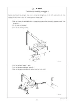
Page 259: ... 230 22 Crane operation when the outriggers are used ON OFF ...

Page 260: ...load values in the lifting capacity chart are based on the assumption that the crane is supported on the level by the outriggers Therefore the strength of the ground where the outriggers are set is one of the most important factors for safety In some working positions as much as 80 of the total mass of the crane plus the suspended load may act through a single outrigger creating an enormous surfac...

Page 261: ...urther 3 Ground which appears to be strong can have dangerously inadequate strength due to ground conditions below the surface Avoid areas which are likely to suffer such problems as listed below and set the outrigger floats on steel plates etc of adequate areas and rigidity to guard against potentially weak soil Surfaces paved with plain asphalt Surfaces paved with thin concrete Brick or cobbled ro...

Page 262: ... place plates etc under the outrigger floats until all tires are off the ground 9 After you have finished setting the outriggers check that each outrigger float is in contact with the ground Also check that the ground is not deformed the floats have not sunk down and the road shoulder is not crumbling 10 Set the outrigger status and boom status that will be used next on the ACS working status setting s...

Page 263: ...se these switches to specify which of the outriggers you will be operating When you press a switch a pip confirmation tone sounds and the indicator lamp for the selected position lights When the left outrigger is selected the lamp color is orange When the right outrigger is selected the lamp color is green For combined operation press to light the indicator lamps in all four positions To cancel a s...

Page 264: ...l the confirmation tone sounds If the extension retraction switch is not used within 30 seconds all position selections will be canceled They will also be canceled immediately if the PTO switch is turned OFF Outrigger operation is only possible when the outrigger operation OK indicator lamp is lit T217161 118 0E 3 If the outrigger beam is extended by 40mm or more when the PTO switch is at the OFF p...

Page 265: ...outrigger selection switches are not selected the horizontal selection switch or vertical selection switch is black indicating that selection is unavailable If one or more outrigger selection switches are selected the horizontal selection switch or vertical selection switch is white indicating that selection is available Press the switch firmly until the confirmation buzzer sounds If the extension r...

Page 266: ...leveling direction leveling is started by selecting the leveling assist switch The switch is enabled when white or disabled when black The outriggers will move vertically to move the indicator toward the center of the inclination monitor while the leveling assist switch is selected Movement stops when the indicator enters the center circle red in the inclination monitor The outer circle on the inc...

Page 267: ...switch is not selected the extension retraction switches are black indicating that selection is unavailable When you extend or retract the outriggers the ACS outrigger setting status will be canceled and the ACS will switch to the working status setting screen When you have used the outrigger control switches insert the outrigger stopper pins and check the outrigger extension widths and check that...

Page 268: ...gger operation switch 3 Left front outrigger operation switch 4 Right front outrigger operation switch 4 All outrigger operation switch This switch is used to operate all four outriggers at the same time Switching it ON operates all four outriggers regardless of the individual operation switch positions If the extension retraction switch is operated when this switch is ON the engine speed increase...

Page 269: ... crane position is in a boom length and boom angle as indicated on the capacity chart for pick and carry operation If the ACS boom operation status is set to jib setting 2 Extract all four stopper pins from the outriggers 3 Extending the four outrigger beams 1 Extend the outrigger beams as far as the marks for the desired length full or intermediate extension When each outrigger beam reaches the d...

Page 270: ...ot insert the stopper pin properly use the extension retraction switch to extend or retract the outriggers repeatedly until the pin has been inserted firmly NOTE When you operate the outriggers from the operator s seat adjust the engine speed with the accelerator pedal to keep a suitable speed of operation 3 Position the outrigger plates under the outrigger floats 4 Vertical cylinder extension ...

Page 271: ...he outrigger beams Check that four tires are not touching the ground 491A 0048 2E 5 Leveling the body Watch the level gauge to level the body with as few operations as possible The data for each outrigger extension widths is set to the ACS automatically but always insert the stopper pin into each outrigger beam and check the extension widths Check that the positions of the stopper pins match the o...

Page 272: ...Check that the outrigger operation OK indicator lamp is lit Conditions for lighting If the crane position is in a boom length and boom angle as indicated on the capacity chart for pick and carry operation If the ACS boom operation status is set to jib setting 2 Extract all four stopper pins from the outriggers If you cannot take an outrigger stopper pin out retract the vertical cylinder first Once ...

Page 273: ...rtical cylinder retraction Move the selection switch to the vertical side and the extension retraction switch to the retraction side to retract the vertical cylinders fully Do not retract the outrigger beam while the vertical cylinder is extended 541A 0183 2E ...

Page 274: ...t the outrigger beams fully 3 Check that all outrigger beams are fully retracted 5 After you have confirmed that the outriggers are fully retracted insert all four stopper pins 6 Stow the outrigger plates in the specified location install the stoppers to prevent the plates from falling out then secure them with the quick pins Be careful of pinching your hands when stowing the outrigger plates Always...

Page 275: ...et the hook stowage mode to the ACS Always refer to the separate ACS instruction manual for ACS operation For the details always refer to the separate ACS instruction manual for confirmation 061A 0048 1E 1 Set the outrigger status on the working status setting screen Check that the outrigger display on the ACS conforms to the outrigger status of the actual machine 2 Set the boom operation status on...

Page 276: ...ed T217321 041 0E 6 Lower the auxiliary wire rope slowly Next lower the main wire rope slowly 7 When hook releasing is complete press the hook stowage mode selection switch yellow Then the switch color is changed to green and the hook stowage mode is canceled 8 Adjust the crane position and perform the ACS preoperational checks Then set the outrigger status and boom operation status appropriate fo...

Page 277: ... for confirmation 061A 0048 1E 1 Make sure that either boom operation mode or rooster operation mode has been set 2 By setting the fully retracted boom length and the boom angle of 11 degrees or less the hook stowage mode selection switch green is displayed on the following ACS screen The hook stowage mode selection switch green is not displayed unless the boom is fully retracted the boom angle is ...

Page 278: ...tch yellow is pressed again the hook stowage mode is canceled and returned to green display T217321 044 0E 3 Slowly wind up the main hook until the mark on the main hook stowage bracket is hidden behind the tension rod Then slowly wind up the auxiliary hook until the overhoisting detector weight lightly contacts the auxiliary hook stowage bracket Take care to avoid overhoisting so that the hook ma...

Page 279: ...the stoppers 6 When the ropes hit the stoppers stroke the levers fully with the engine in the idle status and apply tension to the wire ropes 7 Visually check that the boom is completely housed on the boom rest 8 Hook the chain of the overhoisting detector weight on the auxiliary wire rope side to the chain stowage hook Lowering the boom in the forward direction could cause the jib to contact the ...

Page 280: ...preoperational check should be conducted when all outriggers are fully extended for maximum safety If you will not be able to fully extend the outriggers in the actual work site move to a more spacious area first extend the outriggers fully and conduct the ACS preoperational check 491A 0078 1E Always follow the specified procedure and precautions strictly to set the machine in its working configurat...

Page 281: ... not be possible If the outriggers are not used the working area or the lifting capacity differs greatly from those when the outriggers are used Check the relevant lifting capacity chart before you start work The crane s lifting capacity depends on the crane body being level even when the outriggers are not used However it is difficult to keep the body level without the outriggers so be sure to choos...

Page 282: ...ence to the lifting capacity chart for stationary crane on rubber operation 5 Apply the parking brake and the brake lock at the same time When the pressure in the compressed air tank falls while the brake lock is in use and the foot brake cannot operate a buzzer will sound Before you are going to use the foot brake again you must raise the engine speed to recharge pressure in the tank to the rated...

Page 283: ... to the values in the relevant lifting capacity chart 3 Recheck the tire pressure 4 Lock the suspension 5 Set the ACS working status Set the stationary crane on rubber operation on the working status setting screen Any mistake in setting the ACS working status can be extremely dangerous 6 When you have finished setting the ACS working status proceed with crane operation In stationary crane on rubbe...

Page 284: ... and above strict observance of the conditions for the operation Take adequate precautions trying to foresee dangers keeping all other personnel away from the crane and posting guides to supervise the operation Choose a path for pick and carry operation which is firm level and without major irregularities Never change the direction during pick and carry operation Choose a path which will allow you...

Page 285: ...orking status setting screen Any mistake in setting the ACS working status can be extremely dangerous 6 Apply the slewing brake to immobilize the slewing upper structure 7 Select Low range with the high low speed switch 8 For pick and carry operation the running speed should be slower than 2km h Set the shift lever to speed 1 and strictly observe the running speed less than 2km h 9 When you have fi...

Page 286: ... front and outriggers stowed 2 Suspension Suspension cylinders are fully retracted and locked mode 3 PTO switch ON position 4 Slewing table Slewing brake engaged 5 Driving peed Low speed Moving within a site to change working positions is within the scope of crane operations Therefore even if it involves driving leave the suspension locked and the PTO switch ON as well If the machine is moved with...

Page 287: ... the crane and inset the stopper pins in each outrigger to check the extension width 2 Check that all tires are lifted off the ground 4 ACS setting 1 Set the outrigger setting status that corresponds to the outrigger extension width on the working status setting screen 2 Set the boom status that corresponds to the boom operation status on the working status setting screen 3 Press the ACS display sw...

Page 288: ... the release position intentionally when operating the crane the crane tipping over or other serious accident can be caused T218351 094 0E 7 Control lever position Sit in the operator s seat and tilt the control levers boom derricking lowering lever and winch levers forward to their operating position and secure them in place 8 Length of control levers Loosen the lever length adjustment grip and a...

Page 289: ...P B are not indicated on the display screen of fuel consumption during crane operation T217051 068 0E 3 Level gauge confirmation screen switch If the maintenance screen is displayed when the PTO mode is selected the tilt display is shown To display fuel consumption select the switch to display the fuel consumption display screen If the PTO mode is OFF the fuel consumption screen is displayed and th...

Page 290: ...tely to avoid danger such as by derricking the boom retracting the boom lowering the load or reversing the slewing direction 3 If an error number is displayed in the display window on the ACS screen inspect the corresponding problem If the problem cannot be resolved immediately contact your authorised KATO dealer 4 Always follow the ACS precautions indicated in 20 3 3 5 Outrigger floats lifting off ...

Page 291: ...g the boom without using outriggers make sure the correct outrigger status is selected in the ACS working status setting screen If the boom is derricked when settings are specified for pick and carry operation or stationary crane on rubber operation an upper angle limit will automatically stop the boom from being derricked to prevent tipping backward However if outrigger use is specified and the bo...

Page 292: ...om contacting the boom rest If the boom is lowered below horizontal in any other area than shown below be especially careful not to damage the engine cover mirror fender or other parts When the boom is lowered down to a low angle warning is given with sound pip and display on the ACS screen if the boom or the jib enters into the hazardous zone where it interferes with the engine cover mirror or fe...

Page 293: ...hook is close to the boom top If the boom angle is lowered below the critical angle such as when extending the boom or attaching a jib the crane can tip over even if it is not lifting a load For more information about the critical angle refer to the lifting capacity chart If the boom is derricked when the crane is overloaded the ACS emits a voice warning and warning sound to warn that the crane is...

Page 294: ... is selected by this switch is detected during winch operation and a buzzer will sound to indicate that the winch drum is rotating NOTE The buzzer sound is the same for hoisting and lowering NOTE The buzzer is emitted proportionally faster as the drum rotation speed increases until it eventually stops sounding once a continuous sound is emitted 3 Winch high speed lowering switches If the winch is ...

Page 295: ...rom below the ground or working with a long boom refer to the table for wire rope standard number of parts and use the adequate number of parts for the boom length with which you are working Do not operate the winch at high speed when lifting a load Doing so is dangerous Never drag a load sideways pull it towards the crane or operate the lever suddenly Doing so is dangerous In particular beware of...

Page 296: ...ion lever is pulled upward The boom is extended when the boom extension retraction lever is pressed downward 1 Extending boom sections 2 and 3 1 Confirm that the main and auxiliary hooks are lowered sufficiently below the boom 2 Tilt the boom extension retraction lever in the direction of extending the boom or depress the boom extension retraction pedal forward NOTE For shock reduction at the time of...

Page 297: ...6 extension retraction button NOTE For shock reduction at the time of stopping operate the boom at a slow extension speed after the boom is extended to about 26 5m 2 Retracting boom sections 4 5 and 6 1 Confirm that the main and auxiliary hooks is not lowered more than necessary below the boom 2 Tilt the boom extension retraction lever in the direction of retracting the boom while pressing the boom...

Page 298: ...ever to the neutral position once then retract the boom slowly T217321 033 0E If you extend or derrick the boom while the hydraulic oil is hot and then leave it to rest the extended cylinder may retract as the oil cools This is because the volume of oil has reduced and is not a malfunction The degree of cylinder retraction depends on the amount of change in the oil temperature and the cylinder str...

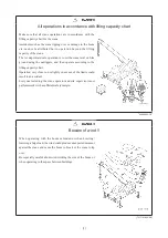
Page 299: ... 270 24 Crane operation NOTE Extension retraction sequence for each boom length ...

Page 300: ...sed from the boom rest before slewing Perform slewing operations gently Sudden lever operations can be dangerous especially when starting and stopping Use extra caution when slewing the crane without all outriggers fully extended as the crane capacity could vary depending on the operating region If a Caution when slewing warning is generated from the ACS during slewing slow down to allow stopping ...

Page 301: ...ng is given with sound pip and display on the ACS screen if the boom or the jib enters into the hazardous zone where it interferes with the engine cover mirror or fender In such a case stop slewing to the hazardous side or lowering operation T217321 168 0E NOTE If the PTO switch is switched OFF the slewing horn will not sound and the slewing brake will be automatically engaged regardless of the sl...

Page 302: ...to never overload the crane Failing to use adequate caution and continuing to slew the machine when overloaded could cause the crane to tip over and result in tragic consequences T217161 059 0E 24 6 1 Slewing operations and system action 511A 0031 2E Actions by the slewing stop system depend on the crane status when overloaded or slew restricted region is specified in the ACS as indicated below 1 S...

Page 303: ...mum lifting capacity will be emitted one time Just before stopping a warning chime DING DONG DANG DONG is emitted continuously to notify the operator that the system is functioning If the control lever is operated in the opposite direction and the crane is slewed away from the overload point angle the warning chime will stop Slewing position slewing angle Voice warning Warning sound Slewing status...

Page 304: ...n while slewing decelerates before automatically stopping slewing will stop then when the slew position starts moving away from the restricted region the warning sound will stop If the voice warning message Caution when slewing is emitted and slewing begins automatically slowing down try to stop slewing manually before reaching the slew restricted region by operating the slewing lever in the oppos...

Page 305: ...request repair Even if the slewing stop system is functioning normally slewing may stop automatically under the conditions indicated below such as an unlevel machine or strong winds 1 Situations where slewing may automatically stop when operating within rated load limits and slewing range limits If slewing stops automatically even though the ACS safety level bar graph or slewing restriction region...

Page 306: ...one beep warnings assuming the ACS is functioning normally NOTE If the ACS emergency switch is used to release the slewing stop system inertial slewing drift is controlled based on the slewing free lock switch position located on the side panel 2 If slewing does not stop when overloaded If the crane is level and yet slewing does not automatically decelerate when the safety level bar graph approach...

Page 307: ...atch on the load movement and let the engine idle 2 If slewing doe not decelerate adequately and appears as though slewing will not stop before entering the restricted region forcibly stop the slewing motion by operating the lever in the opposite direction being careful not to let the load swing 3 If it is necessary to slew close to the restricted region double check the distance to any obstructio...

Page 308: ...arning chime or emergency sound is emitted according to how far it slewed into the restricted region to notify the operator of the danger In addition even if slewing is reversed to escape the restricted region the warning sound will continue until the crane is no longer in the restricted region Slewing operation Slewing position Voice warning Warning sound Continuing to slew in same direction Poin...

Page 309: ...efully As a result of lowering the jib the work radius is extended Take care to avoid excessive load Do not pull a load transversely or draw it closely by means of derricking the jib 541A 0244 0E 2 Power jib derricking lowering lever lock This is used to lock the power jib derricking lowering lever when it is not operated for preventing incorrect operation The power jib derricking lowering lever i...

Page 310: ...number of parts above If the work site is below the ground the length of the winch wire rope may become inadequate for the boom length used In that case reduce the number of parts of line so that at least three turns of the wire rope remain on the winch drum When hoisting from below the ground the length of the wire rope required is equal to the number of parts of line multiplied by the distance b...

Page 311: ...lly and slew it to the side or front 2 Remove the rope retaining bracket located at the segment on the left side of the boom top 3 Detach the rope socket 4 Remove the rope socket from the rope 5 Detach the wire rope from the overhoisting detector weight 6 Change the number of the wire ropes NOTE Use the wire guide to route the wire rope through the hook sheave ...

Page 312: ...u route the wire rope through the hook according to the wire rope number of the parts repeat steps 1 to 3 described above 5 Pull the wire guide out of the hook After you change the wire rope number of parts be sure to pull the wire guide out of the hook If you operate the winch or crane with the wire guide inserted the wire rope and hook could be damaged Also the wire guide could fall from the hoo...

Page 313: ... tangled on the drum The rope socket should be attached in the orientation shown below 541A 0249 2E Base the wire rope standard number of parts on the table for the wire rope standard number of parts Take care not to tangle the wire rope The rope socket and clip should be attached as shown in the diagram below 541A 0250 1E Refer to Wire rope handling in the inspection and servicing section for the...

Page 314: ... T218711 005 0E Preoperational checks Pre drive checks 218711 26 Preoperational checks Pre drive checks 285 26 1 Pre drive checks 286 26 2 Preoperational checks 293 ...

Page 315: ...ls stated in the inspection and servicing table are based on the elapsed time indicated by the hour meter Follow both the passage of dates and of hours of operation and carry out each inspection item when one of the times is reached whichever occurs sooner If you discover any damage breakdown or malfunction repair it immediately Do not leave it for later and do not start work before it is repaired...

Page 316: ...ir pressure Check the tire pressure with a tire gauge while the tires are still cool before driving anywhere Adjust the pressure as necessary to the rated pressure Do not stand in front of the tire during adjustment because the tire may burst Check that there is no damage to the sidewalls and no cracks or abnormal wear to the treads Replace any tires which have exposed canvas regardless of their a...

Page 317: ...ap from the top of the reserve tank and add coolant Total coolant volume about 30L Engine 11 2L Radiator 7 2L Sub tank 5 3L Torque converter cooler 2 5L Piping 4L Devices to prevent diversion of smoke malodorous gas and hazardous gas Device to prevent diversion of carbon monoxide and other gases Looseness of installation and damages on exhaust gas reduction devices such as catalytic reactor Check ...

Page 318: ...art Air compressor Condensation in the air tank Rear view mirrors and reflectors Image status When sitting in the cab always adjust the mirror positions and clean them if necessary to get an adequate field of view Location of anything unusual noticed during driving Check for any problems at corresponding location Others Oil leakage from any part of the chassis T218351 089 0E ...

Page 319: ...Preoperational checks Pre drive checks 26 Preoperational checks Pre drive checks 289 26 1 2 Points for pre drive checks 511A 0076 0E ...

Page 320: ...26 Preoperational checks Pre drive checks 290 ...

Page 321: ...Preoperational checks Pre drive checks 26 Preoperational checks Pre drive checks 291 ...

Page 322: ...26 Preoperational checks Pre drive checks 292 ...

Page 323: ...an belt slack Inspect Excessive slack in the fan belt can cause overheating and inadequate generation by the alternator Excessive tension can damage the engine bearings and snap the fan belt Check the tension of the fan belt and adjust it if necessary Oil pan Engine oil Check oil level Check the engine oil when the machine is parked on the level Use the level gauge to check the level of the engine...

Page 324: ...eakage Inspect Responsivity Inspect Hydraulic pump Oil leakage Inspect Abnormal noise Inspect Oil cooler Oil leakage Inspect Rotary seal Oil leakage Inspect Hydraulic valve Oil leakage Inspect Slewing related Slewing gear Bearing Abnormal noise on slewing Inspect Slewing brake action Inspect Move the slewing brake switch to the brake side then check that the slewing upper structure does not slew e...

Page 325: ...e limit of wear indicator is visible There are six points at a depth of 1 6mm spaced around the circumference of the tire which serve to indicate when the limit of wear has been reached Air pressure 900kPa 9 00kgf cm2 Tire size 325 95R24 162 160K Crack damage abnormal wear Inspect Lodged metal fragments stones etc Inspect Wheel nut Inspect Check that none of the wheel nuts is loose If any are loos...

Page 326: ...etc light normally Turn the headlamps on and use the lever on the right side of the combination switch to switch between high beam and low beam At the same time check that the high beam indicator lamp lights at the right time Use the lever on the right side of the combination switch to check that all the turn signal lamps on the machine light normally and at the same time confirm that all indicator...

Page 327: ...tial start screen is displayed on the information display Cluster meter panel Inspect Check that the indicator lamps do not indicate any problem If there is any problem you must stop the engine and investigate the cause Entry key system Check action Touch the IC tag to check whether the engine can be started Action of the door and cover locks Inspect Crane safety devices ACS Inspect The ACS automa...

Page 328: ...26 Preoperational checks Pre drive checks 298 26 2 2 Points for preoperational checks T217221 051 0E ...

Page 329: ...Preoperational checks Pre drive checks 26 Preoperational checks Pre drive checks 299 ...

Page 330: ...26 Preoperational checks Pre drive checks 300 ...

Page 331: ...Preoperational checks Pre drive checks 26 Preoperational checks Pre drive checks 301 ...

Page 332: ... 302 MEMO ...

Page 333: ...5 Auxiliary brake indicator lamp 117 Auxiliary brake lever switch 153 Auxiliary winch high speed lowering switch 219 Auxiliary winch lever 218 Auxiliary winch pedal 219 B Battery charge indicator lamp 119 Boom derricking lowering lever 218 Boom extension retraction emergency switch self reset type 214 Boom extension retraction lever 217 Boom extension retraction pedal 218 Boom guard 170 Boom secti...

Page 334: ...er oil temperature 132 Display screen of fuel consumption during crane operation 260 Door 13 Door open lock 13 Driving direction display of the lower structure 124 Drum rotation detector switch 219 E Eco switch 136 261 Engine cover 28 Engine diagnostic indicator lamps 27 Engine oil warning lamp 124 Engine stop emergency switch 213 Engine trouble warning lamp red 116 Engine trouble warning lamp yel...

Page 335: ...lever 151 High beam indicator lamp 115 High low speed switch 134 Holders for the instruction manual 19 Holders for the lifting capacity chart 19 Hook displacement display setting buttons 218 Horizontal vertical selection switches 236 Horn switch 151 Hour meter 114 Hydraulic oil warning lamp 129 I Idling level switch 136 Indicator section 115 128 Information display 128 Initial screen display switc...

Page 336: ... Message display 125 Meter section 113 Mirror heater switch optional 148 Multiplex communication error warning lamp 128 O Odometer 114 Odometer trip meter switch 114 Operator s seat 14 Outrigger control panel 221 234 Outrigger control panel lamp 222 Outrigger control switches inside the operation cab 234 Outrigger emergency switch self rest type 222 Outrigger extension retraction switch 238 Outrig...

Page 337: ...ering lock release confirmation indicator lamp 130 Rear steering lock release indicator lamp 120 Rear steering locked lamp 156 Rear steering switch self reset type 149 Rear view camera color 58 Rear view camera mode switch 59 Reclining lever 14 Roof window wiper washer switch 25 S SCR cleaning cancel indicator lamp 130 SCR cleaning cancel switch 133 SCR system 87 SCR system cleaning indicator lamp ...

Page 338: ...pension control switch 144 Suspension locked indicator lamp 130 Suspension operation OK indicator lamp 129 Switch section 131 T Tachometer 114 Temperature voltage confirmation and fuel consumption display screen mode switch 131 Tilt lever 220 Toolbox 29 Torque converter trouble warning lamp 117 Trip meter 114 Trip setting switch A B for fuel consumption during driving 139 Turn signal and dimmer swi...

Page 339: ...justment dial 15 Wheel chocks optional 31 Winch camera color Winch light 58 Winch lever lock 220 Winch lighting switch 215 Windows 18 Windscreen washer switch 152 Windscreen wiper switch 152 Wireless rear view camera optional 59 Working lamp indicator lamp 128 Working lamp switch 214 ...

Page 340: ... 310 MEMO ...

Page 341: ... chome Shinagawa ku Tokyo 140 0011 Japan Tel Head Office Tokyo 03 3458 1111 Overseas Marketing Department Tokyo 03 3458 1115 Fax Tokyo 03 3458 1163 URL http www kato works co jp 180213TI 7 2018 50 GD 1 4 2019 10 GD 1 1 1 ...

Page 342: ...899 92187110 ...

Reviews: