3-2 OPERATION
_______________________________________________________________________
Copyright © 2011 by Kaufman & Robinson, Inc., 1330 Blue Spruce Drive, Fort Collins, CO 80524
Tel: 970-495-0187, Fax: 970-484-9350, Internet: www.ionsources.com
DISCHARGE POWER SUPPLY MANUAL
MODEL DC3005, MODEL 30010, MODEL 15012
given time. The load will determine the other. Example: If the Discharge set-
points are 5 amps and 200 volts and the load is 25 Ohms then the output will
be limited to 5 amps and the output voltage will be 5x25 = 125 volts according
to Ohms law (V = IxR). If the Load resistance is 50 Ohms then the output will
be limited to 200 volts and the current will be 200/50 = 4 amps. The Discharge
control offers automatic and extremely fast crossover between Voltage and Cur-
rent regulation.
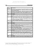
Local/Remote
switch – Selects Local (front panel) or Remote (analog or RS-
232) control.
Amps/Volts
Select – Selects which parameter is being adjusted by the setpoint
adjust encoder knob as indicated by the amps or volts light.
Discharge Volts
display – Displays the measured discharge voltage in volts.
Discharge Amps
display – Displays the discharge current setpoint and run val-
ues in amps. When the yellow setpoint indicator below the display is illuminated,
the setpoint value is displayed. When the green run indicator is illuminated, the
run value is displayed.
Setpoint
indicator – Indicates when the setpoints are being displayed on the
Digital Displays. When the yellow setpoint indicator below the display is illumi-
nated, the setpoint value is displayed. When the green run indicator is illumi-
nated, the run value is displayed.
Run
indicator – Indicates when the running values are being displayed on the
Digital Displays.
Setpoint Adjust
knob – Adjusts the Voltage and Current setpoints when in local
mode.
3.2 Remote Mode RS-232
Operation of the Discharge Power Supply in Remote mode requires the mode
selector switch, located on the front panel of the Power Supply, to be switched
to Remote.
The Discharge Power Supply can be operated from a host computer using an
RS-232 port on the computer. Connection from the computer is made from a
serial port on the computer to the serial port on the Discharge Power Supply,
labeled, “RS-232”, “Discharge”. This approach uses an RS-232 straight through
cable that connects to a DB-9 male connector. This approach allows the user to


