OPERATION 3-7
_______________________________________________________________________
Copyright © 2011 by Kaufman & Robinson, Inc., 1330 Blue Spruce Drive, Fort Collins, CO 80524
Tel: 970-495-0187, Fax: 970-484-9350, Internet: www.ionsources.com
DISCHARGE POWER SUPPLY MANUAL
MODEL DC3005, MODEL 30010, MODEL 15012
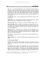
Supply and the value of 2048 was returned from the terminal program.
To convert this value to the output voltage, divide 2048 by 4095 and
multiply by 300 volts for model DC30010 power supply.
3.3 Remote Mode Analog
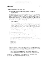
The Discharge Power Supply can be operated using analog.
3.3.1 ANALOG Input/Output
The Discharge Power Supply can be remotely controlled using a 0-5 volt DC
analog interface. The analog remote uses 0-5 volt signals for controlling and
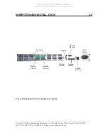
monitoring the Power Supply. There is one 25 pin female D connector la-
beled ANALOG on the back of the Power Supply for connection to the analog
interface. The pin descriptions for the interface are given below in table 1.
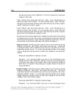
There is a button on the front panel that can be used to switch from remote
to local control. There is also a two pin Molex connector on the back panel
labeled INTERLOCK. The pin descriptions for the interlock are also given
below in table 3-4.1.
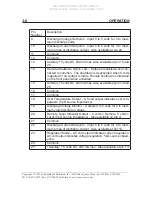
Table 3-4 Analog connections.
Pin
Number
Description
1
Output Enable – Output is enabled when 5 volts is applied.
Output goes to standby mode when 0 volts is applied or when
no contact is made. Enable and Standby are indicated on the
front panel.
2
Remote Shutdown, Active High – Output is disabled when 5
volts is applied. The shutdown is deactivated when 0 volts is
applied or no contact is made. Remote Shutdown is indicated
on the front panel when activated.
3
Common.
4
Remote Local Indicator Output – 0 volts = Remote, 5 volts =
Local (5 k
Ω
source impedance). Also available on pin 20.
5
No Contact.
6
Common.
7
Discharge Current Monitor – Outputs 0 to 5 volts for 0 to maxi-
mum amps of discharge current.
8
No contact


