background image

LINK

net

™  

!

  USER MANUAL 

DCM000000008


Printed:  00.03.22,09:08 


Revision Date:3/22/00 

   9


Location: 

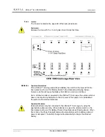
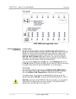
The Fuse is located on the upper left of the back plane board. . 

Replacement: 

Replace the fuse with 1¼ x ¼-inch glass fuse 8 Amps fast blow.  


Operation without batteries 

If the LINK

net

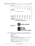
™ is being used without a Battery the switch on the lower left of the 

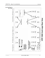
back plane must be set for “Battery Absent” (See Back plane Drawing below). 
Failure to do this will cause the Battery Fail LED to remain on at all times. 

Note:  Without a battery connected to the LINK

net

™ Card-cage, the system will shut 

down or reset with any disruption to the AC power. When power is re-established 
the system will restart automatically. 

Operation with batteries 

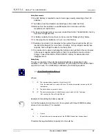
External batteries may be connected to the LINK

net

™ Card-cage, by using the 

appropriate cable assembly.  When batteries are used, the selector switch on the 
back plane must be set for Battery Present (See Back plane Drawing above). When 
this is done, the Power Supply Module will automatically switch to battery when AC 
power is disrupted. The battery charger will automatically recharge the attached 
battery. 

Fuse 

Batteries 


Summary of Contents for LINKnet OFR1000

Page 1: ...N D I N S T A L L A T I O N O P E R A T I O N A N D I N S T A L L A T I O N O P E R A T I O N A N D I N S T A L L A T I O N O P E R A T I O N A N D M A I N T E N A N C E M A I N T E N A N C E M A I N T E N A N C E M A I N T E N A N C E KAVAL TELECOM INC 60 Gough Road Markham Ontario L3R 8X7 Telephone 888 86 KAVAL Web www kaval com E mail info kaval com Document DCM00000008 Rev 2 ...

Page 2: ...f the owner or licensee of this document without the prior written consent of KAVAL TELECOM INC is strictly prohibited KAVAL TELECOM INC provides this document as is without any warranty of any kind either expressed or implied including but not limited to the implied warranties of merchantability and fitness of a particular purpose KAVAL TELECOM INC may make changes or improvements in the equipmen...

Page 3: ...ase All Draft Issues Feb 2000 1 All Original Release Mar 6 2000 2 All Updated drawings and Logos Mar 21 2000 T T T T T T T T R R R R R R R R A A A A A A A A D D D D D D D D E E E E E E E E M M M M M M M M A A A A A A A A R R R R R R R R K K K K K K K K N N N N N N N N O O O O O O O O T T T T T T T T I I I I I I I I C C C C C C C C E E E E E E E E This manual makes reference to trademarks that are ...

Page 4: ...FUSE 9 Location 9 Replacement 9 BATTERIES 9 Operation without batteries 9 Operation with batteries 9 Battery Requirements 10 Battery Sizing 10 Battery Cable 11 Battery Charge Time 12 Battery Maintenance 12 6 PHYSICAL INSTALLATION 13 CARD CAGE ENCLOSURE 13 POWER SUPPLY 13 AC Power Connection 14 BATTERY 14 Battery connection 14 RF MODULES 15 EXPANDING THE SYSTEM 15 Additional Modules 15 Additional L...

Page 5: ...he system Text in BOLD CAPITALS refers to buttons indicators or connectors on the operator console or the specifically indicated panel The exclamation mark icon appears next to text of critical importance Failure to read these items may result in damage to equipment or personnel The STOP Icon appears next to critical steps in procedures Failure to precisely follow these steps will cause damage to ...

Page 6: ...tem This module is optional Daisy chained Multiple Card cages may be cascaded or joined to form a large system Expansion cable Custom wiring harness to interconnect multiple Card cages Hot swap RF Modules may be inserted or removed while the system is operational Power Supply Module A Self contained Power Supply Module specifically designed to be inserted into the LINKnet platform Card cage PS Pub...

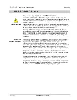
Page 7: ...ses the functionality of most of KAVAL TELECOM INC s current electronic product line All OFR and BDA products are harmonized into a single modular and adaptable system The intention is to incorporate the functionality of most or all of KAVAL TELECOM INC s product line into a single modular family Newer technology allows implementation of additional features such as Digital Control Self alignment a...

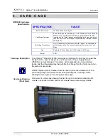
Page 8: ...k Mount 6U 10 5 High 14 00 Deep Weight TBD The LINKnet Model OFR1000 card cage is a standard 19 inch rack mounted box 6U high 10 5 and 14 deep The unit comes with a Power Supply Module PS400A and will hold up to 7 modules All modules slide in on pre installed tracks and their faceplates together with the front flange form the front cover when the system is assembled OFR000 Spacer blank modules mus...

Page 9: ...LINKnet USER MANUAL DCM000000008 Printed 00 03 22 09 08 Revision Date 3 22 00 5 Card Cage Drawing Rear View ...

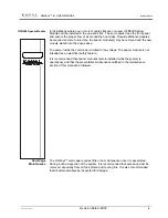
Page 10: ... power inside the card cage is limited to low voltage The spacer module is not intended as an electrical safety feature It is recommended that spacer modules remain installed while the system is operational and that the preventative maintenance outlined in the maintenance section of this manual be followed The LINKnet card cage requires little or no maintenance once it is assembled During routine ...

Page 11: ...LINKnet USER MANUAL DCM000000008 Printed 00 03 22 09 08 Revision Date 3 22 00 7 This module is optional 4 C O N T R O L M O D U L E ...

Page 12: ...when AC absent and platform is being powered externally AC FAIL Red OFF ON Illuminated when AC power present but no external power source present Note this LED can be disabled if a secondary power source is not required Battery FAIL Red OFF Under normal operation the AC On LED Green will illuminate and will remain on when power is connected If there is a power disruption and there is a secondary p...

Page 13: ... remain on at all times Note Without a battery connected to the LINKnet Card cage the system will shut down or reset with any disruption to the AC power When power is re established the system will restart automatically Operation with batteries External batteries may be connected to the LINKnet Card cage by using the appropriate cable assembly When batteries are used the selector switch on the bac...

Page 14: ...ter than is inherent in the power supplies internal system then it is possible to use an external charger Consult the KAVAL TELECOM INC factory for details at E mail info kaval com BatterySizing The size or capacity of the external lead acid batteries is dependent on two variables The number of modules installed in the Card cage and the desired back up period in hours The relationship is defined b...

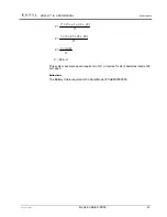
Page 15: ...09 08 Revision Date 3 22 00 11 15 3 2 1 5 p p p T C 15 45 45 45 5 3 C 15 140 3 C C 28 A H This system example would require two 12V in series for 24V batteries rated at 28 A H each BatteryCable The Battery Cable required is the Kaval Model CAB000000055 ...

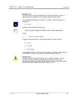
Page 16: ...eries in the example system above Where C 28 AH From the above example Therefore the required time to recharge the batteries in hours would be C T 2 1 28 2 1 T 6 33 T Hours It would take 33 6 hours 33 hours and 36 minutes to recharge a system that had three OFR800 modules and required a 3 hour battery power reserve BatteryMaintenance In order to ensure the proper functioning of your LINKnet system...

Page 17: ...NKnet If several units are installed in the same rack an external fan blowing air past the heat sinks is recommended The LINKnet is intended for indoor use only in an environment suitable for electronic equipment Do not expose to excess humidity Slide the power supply module into the right hand slot of the LINKnet rack Make sure that the Module is aligned with the guide tracks on the Card cage and...

Page 18: ... side of the back plane See diagram below Batteryconnection If Batteries are to be installed Set the Battery DIP Switch to the OFF position The switch is located on the left hand side of the back plane See diagram below Make sure the batteries have been correctly sized See section on sizing Batteries Make sure that the batteries have been properly mounted See Battery Manufacturer s Installation In...

Page 19: ...The edge connector and the antenna connectors at the rear of the module must be seated securely and evenly Tighten the retaining screws to secure the module The Module is now ready for testing See Power On Self Test It is not necessary to power down the system to insert or remove RF modules as each module is designed with Hot Swap capabilities Do not force the module into position It should slide ...

Page 20: ...ach enclosure must have a unique Card cage ID number set by the rotary switch located on the lower left hand side of the back plane If the system has only one card cage this switch can be left at the default setting zero Group Termination The first and last LINKnet card cages must have the termination switch set to ON The switch is located in the lower left hand side of the back plane If the syste...

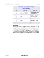
Page 21: ...wn install program From the Windows START button s RUN Menu Use the BROWSE button to find the SETUP program on the disk and follow the on screen instructions When set up is complete there will be a KAVAL TELECOM INC icon on the desktop Cable connections The rear of the LINKnet card cage has a CONTROL PORT CONNECTOR for each of the plug in module bays In order to change the parameters of a specific...

Page 22: ...ing the program The software allows a terminal emulation program to access the digital information stored in the module This same program will be used to modify the parameters in every type of module in the system Since not all modules will have the same types or values for parameters it is very important that the user know the type of module to be changed the types of parameters that may be chang...

Page 23: ...LINKnet USER MANUAL DCM000000008 Printed 00 03 22 09 08 Revision Date 3 22 00 19 Not yet approved for distribution 7 M A I N T E N A N C E ...

Page 24: ...LINKnet USER MANUAL DCM000000008 Printed 00 03 22 09 08 Revision Date 3 22 00 20 Not currently available 8 T R O U B L E S H O O T I N G ...

Page 25: ...itten agreement to such effect executed by an authorized officer of KAVAL TELECOM INC has been entered into This warranty is void if the product has been subject to misuse neglect accidental damage damage of a purely cosmetic nature misapplication extreme environmental conditions unauthorized repair or alteration If warranty repair is required KAVAL TELECOM INC will repair or replace the defective...

Page 26: ...22 00 22 Part Numbers referred to in this Manual Number Description CAB000000055 Battery Connect Cable CAB000000056 Expansion Cable CAB000000057 Control Connector CAB000000058 AC Power Cable DCM000000008 This Manual A p p e n d i x A Q u i c k R e f e r e n c e Part Numbers ...

Reviews: