LINK
net
™
!
USER MANUAL
DCM000000008
Printed: 00.03.22,09:08
Revision Date:3/22/00
13
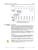
Install the LINK
net
™ card-cage into an EIA 19” rack using 4 screws. Ensure that no
cables or other equipment rests on top of the LINK
net
™ and places an excessive
downward force on the rear of the unit.
The RF Antenna connections are designed for the specific RF unit. They may be
different for each RF module, so they are described in the chapter specific to each
RF module. These instructions must be followed precisely in order to ensure the
safe functioning of the radio transmitter.
Ensure that airflow around the rear panel heat sink is unobstructed. In high duty
cycle installations, it is recommended that one rack unit of clear space be left both
above and below the LINK
net
™. If several units are installed in the same rack, an
external fan blowing air past the heat sinks is recommended.
The LINK
net
™ is intended for indoor use only, in an environment suitable for
electronic equipment. Do not expose to excess humidity
Slide the power supply module into the right hand slot of the LINK
net
™ rack. Make
sure that the Module is aligned with the guide tracks on the Card-cage, and sliding in
straight. The edge connector at the rear of the module must be seated securely and
evenly. Tighten the retaining screws to secure the module, and connect the AC
power to the appropriate connector in the upper left of the Card-cage back plane.
ALERT:
Do not force the module into position. It should slide in with little or no
force. If the module resists, remove it and inspect the slides and the connectors. If
still unable to insert the module contact KAVAL TELECOM INC.
6 . P H Y S I C A L I N S T A L L A T I O N
Card-cage (Enclosure)
Power Supply

