LINK
net
™
!
USER MANUAL
DCM000000008
Printed: 00.03.22,09:08
Revision Date:3/22/00
15
•
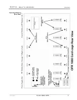
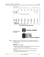
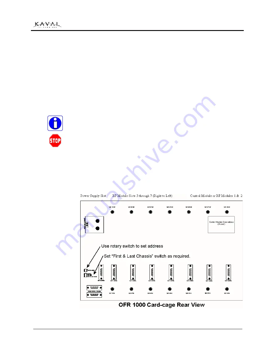
Connect the Battery Connect Wiring Harness to the Battery end, and then connect
the other end to the plug in the upper left of the rear of the Card-Cage (See
diagram below)
•
Calculate the required Charging Time to ensure the Batteries will be charged prior
to system testing. (See section on sizing Batteries)
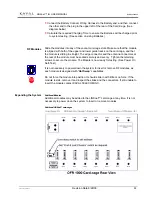
Slide the modules into any of the vacant card-cage slots. Make sure that the module
is aligned with both of the upper and lower guide tracks on the card-cage, and that
the module is sliding in straight. The edge connector and the antenna connectors at
the rear of the module must be seated securely and evenly. Tighten the retaining
screws to secure the module. The Module is now ready for testing. (See Power On
Self-Test)
It is not necessary to power down the system to insert or remove RF modules, as
each module is designed with “
Hot Swap
” capabilities.
Do not force the module into position. It should slide in with little or no force. If the
module resists, remove it and inspect the slides and the connectors. If still unable to
insert the module contact KAVAL TELECOM INC.
Additional Modules
Additional modules may be added to the LINK
net
™ card-cage at any time. It is not
necessary to power down the system to insert or remove modules.
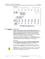
Additional LINK
net
™ card-cages
RF Modules
Expanding the System

