LINK
net
™
!
USER MANUAL
DCM000000008
Printed: 00.03.22,09:08
Revision Date:3/22/00
16
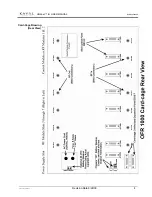
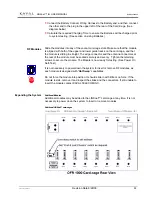
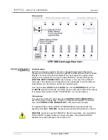
Additional card-cages can be cascaded or “Daisy Chained” together with a Kaval
Model # CAB000000056 Expansion cable. Up to 15 cables can be used to connect
up to 16 LINK
net
™ card-cages. The nominal maximum cable length is 150 feet but,
under certain conditions, a longer span may be possible, contact KAVAL TELECOM
INC. for assistance.
If 16 LINK
net
™ card-cages are connected together the total system capacity is 110
RF modules without the optional Controller Module.
A separate power supply module (PS400A) and battery reserve (if desired) must be
installed for each card-cage as well. Only one (optional) Controller Module per
system is necessary.
Card-cage ID number
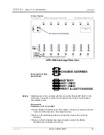
Each enclosure must have a unique Card-cage ID number; set by the rotary switch
located on the lower left hand side of the back plane.
If the system has only one card-cage this switch can be left at the default setting
(zero).
Group Termination
The first and last LINK
net
™ card-cages must have the termination switch set to ON.
The switch is located in the lower left hand side of the back plane.
If the system has only one or two card-cages the switch can be left at the default
setting (ON).
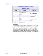
Pins 2 & 3 of the DB15 “Control Port connector & Expansion cable connector”
connect to a dry, normally open, relay contact rated for 1 Amp at 28 Vdc. The
contacts will close if any of the modules in any of the LINK
net
™ card-cages fault,
and will remain closed until the fault is corrected.
Because the LINK
net
™ Expansion cable uses the same connector, this signal must
be taken from the un-used connector on either the first or last panel.
External fault
indication

