
2
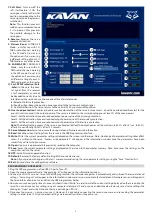
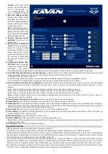
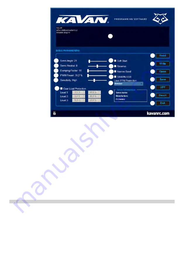
7. Soft Start:
Turns on/off the
soft start feature. If ON, the
servo goes slowly to the initial
position corresponding to the
servo signal once the power is
switched on.
Note:
This function prevents
sudden servo movement once
it is turned on thus prevents
the possible damage to the
servo gears.
8. Reverse:
Reverses the servo
movement direction.
9. Narrow Band:
FUTABA SR
Mode – only for use with FU-
TABA radio channels working
in the SR mode. Do not turn
the option on if you are using
a different setting of your FU-
TABA radio or any other radio.
10. SANWA SSR:
SANWA SSR
Mode - only for use with SA-
NWA radio channels working
in the SSR mode. Do not turn
the option on if you are using
a different setting of your SA-
NWA radio or any other radio.
11. Lost PPM Protection (Fail-
-Safe):
In the case the cont-
rol signal from the receiver
is lost completely or cannot
be decoded correctly (due to
interference) the servo can use choose one of three fail-safe modes:
(a) Release: No fail-safe protection.
(b) Keep Position: Keeps the position corresponding to the last correct control signal.
(c) Go Neutral Position: The servo returns to the neutral (1500 µs pulse width) position.
12. Over Load protection:
Enables or disables overload protection of the servo in three levels – once the overload conditions last for the
pre-set time (in seconds), the output power of the servo is reduced to the corresponding pre-set level (% of the max. power).
Level 1: Set the activation time and reduced output power value of the primary protection.
Level 2: Set the activation time and reduced output power value of the secondary protection.
Level 3: Set the activation time and reduced output power value of the tertiary protection.
Note:
The default setting means: if the servo is overloaded (stalled) the output power will be cut down to 62.7% after 5.1 sec, to 50.2%
after 8.2 sec and finally to 25.1% after 12.2 seconds.
13. Servo Information:
Servo type, manufacturing date and firmware version information.
14. Read:
Read the current settings from the servo via the USB Programmer/interface.
15. Write:
Writes the current parameter settings displayed on the screen into the servo. Note: No change of parameter setting takes effect
unless it is written to the servo. “Success write parameter!” will appear in the information window once the parameters have been
successfuly written into your servo.
16. Open:
Opens servo parameter file previously saved on the computer.
17. Save:
Saves the current parameter settings displayed on the screen to the computer memory. Note: Save saves the settings on the
computer, not into the servo!
18. UPF:
Servo firmware upgrade function.
19. Default:
Restores the factory default setting of the connected servo.
Note:
All your previous changes will be lost – we recommend saving the servo parameter settings using the “Save” function first.
20. Exit:
Exit and close the configuration software.
PROGRAMMING YOUR SERVOS
1. Plug the USB programmer in a free USB 2.0 port of your PC.
2. Open the programmer software, “Adapter plug-in!” will appear in the information window.
3. Connect your GO-10xx series servo to the USB programmer; the software recognizes it automatically and will read the servo data and
settings. “Servo plug-in!” will appear in the information window and servo name, manufacture date and firmware version will appear in
the Servo Information box. Green LED on the USB programmer flashes.
4. Now you can make any adjustments; once satisfied, click on “Write” in order to write the current setting displayed on the screen into the
servo. You can also save your settings on your computer clicking on “Save” or you can download a previously saved servo settings file
clicking on “Open” and write it into another servo clicking on “Write”.
5. Disconnect your servo – now you can use it. However, it is advisable connecting the servo once more and re-reading the parameter
settings in order to be 100% your desired settings were correctly written into your servo.
1
2
3
4
5
6
7
7
9
10
11
12
13
14
15
16
17
18
19
20


