background image

Instructions for use ELECTROmatic M/C and PM/PC

5 Commissioning | 5.1 Connection

Note

The ELECTROmatic has an automatic spray air and spray water shut-off. The
automatic spray air and spray water shut-off prevents the following:
- Dripping of spray water after the motor is stopped
- Continuous exit of water/air through leaky treatment centers

Connect the 4-hole, 5-hole or 6-hole turbine hose of the treatment unit to
the filter of the ELECTROmatic.

or

If the turbine hose of the treatment unit has a 2-hole or 3-hole connector,
replace the turbine hose with a 4-hole, 5-hole or 6-hole turbine hose or use
a commercial adapter available from specialized dealers.

See also:

2

11 Accessories and consumables, Page 73

5.1.3 Connecting the motor

Slightly wet the O-rings on the connection hose with KAVOspray.

Connect the motor to the supply hose and twist.

ð

The correct attachment position is attained automatically.

Screw tight the hose-side union nut proceeding in the direction of the ar-
row.

49 / 80

Summary of Contents for ELECTROmatic M

Page 1: ...Instructions for use ELECTROmatic M C and PM PC ...

Page 2: ...ributed by KaVo Dental Technologies LLC 11727 Fruehauf Drive Charlotte NC 28273 USA Phone 847 550 6800 Fax 847 550 6825 Manufacturer Kaltenbach Voigt GmbH Bismarckring 39 88400 Biberach Germany www kavo com ...

Page 3: ...8 3 3 ELECTROmatic Versions 22 3 4 Motor hose 22 3 5 Control panel PM PC only 23 3 6 Technical specifications of the ELECTROmatic 25 3 7 Symbols on product and rating plate 28 3 8 Power supply type 4882 29 3 9 Technical data for the power supply type 4882 29 3 10Symbols on the nameplate of the type 4882 power supply 30 4 Installation 32 4 1 Location 32 4 2 Installation positions 32 4 3 Preparing t...

Page 4: ...with the SAFEdrive function 60 7 Decommissioning 62 7 1 Disconnecting the electrical connection 62 7 2 Disconnecting the ELECTROmatic from the treatment unit 62 7 3 Unplugging the motor COMFORTdrive 62 8 Processing steps in accordance with DIN EN ISO 17664 63 8 1 Cleaning 63 8 1 1 Preparation at the site of use 63 8 1 2 Manual external cleaning 63 8 1 3 Manual cleaning of the inside 63 8 1 4 Mecha...

Page 5: ...ctromagnetic emission 74 12 2Guidelines and manufacturer s statement Electromagnetic immunity 74 12 3Guidelines and manufacturer s statement Electromagnetic immunity 75 12 4Recommended safe distances between portable and mobile HF telecommunications equipment and the ELECTROmatic 77 Instructions for use ELECTROmatic M C and PM PC Table of contents 5 80 ...

Page 6: ...ns Short IfU Short instructions for use AI Assembly instructions TI Technician s instructions IEC International Electrotechnical Commission RI Repair instructions RK Retrofitting kit AS Assembly set CK Conversion kit EP Enclosed parts EMC Electromagnetic compatibility PI Processing instructions 1 1 2 General marks and symbols See section on Hazard levels Important information for users and technic...

Page 7: ...t in for a service check every two years In this service check the safety checks are performed according to IEC 62353 VDE 0751 1 Please direct all questions regarding the product service and maintenance to the KaVo Technical Service Toll free 1 888 ASK KAVO 888 275 5286 Email techservice kavokerr com Please refer to the serial number of the product in all inquiries 1 3 1 Repair Service For repairs...

Page 8: ...tely reported to KaVo in writing This notification must be accompanied by a copy of the invoice or delivery note on which the manufacturing number is clearly visible In addition to the war ranty the statutory warranty claims of the purchaser also apply with a war ranty period of 12 months Defects and the consequences of defects in particular because of insufficient servicing of the water filter ar...

Page 9: ... claim for damages against the shipping company 2 Leave the product and packaging in the condition in which you received it 3 Do not use the product If the product is damaged but there was no discernable damage to the packag ing on delivery proceed as follows 1 Report any damage to the shipping company immediately and no later than 7 days after delivery 2 Leave the product and packaging in the con...

Page 10: ...ointing upwards Fragile protect against impact Permissible stacking load Stacking limit by number Protect from moisture Temperature range Air pressure Humidity Do not dispose this product into the ordinary municipal waste or garbage system 1 6 Disposal Note Any waste produced must be recycled or disposed of in strict compliance with all applicable national regulations in a manner which is safe for...

Page 11: ...er under the menu item eom Download the disposal order or complete it as an online order 2 Enter the corresponding information to complete the order and submit it as an online order or by fax 49 0 3304 3919 590 to enretec GmbH The following contact options are also available for questions and for initiat ing a disposal order Telefon 49 0 3304 3919 500 Email eom enretec de and Postal address enrete...

Page 12: ...hazard area Electrical sparks in the product can lead to explosion or fire Do not use product in explosion hazard areas Do not operate the product in an oxygen enriched atmosphere Do not use the product in the vicinity of flammable gases 2 3 Technical condition A damaged device or components can injure patients users and third parties A damaged power cable or missing protective conductor can lead ...

Page 13: ...m any ingress of liquids Do not place the product in a trough like container If any liquid is detected on the device disconnect the power cable from the supply mains right away and do not touch the product Make sure that the surface of the product is absolutely dry before plugging the power cable back into the socket After interventions on and repairs of the device and before re use have the servi...

Page 14: ...ing chapter of the present In structions for Use can be performed by the operator user Repairs and safety checks may only be performed by trained service personnel The following persons are authorized to do this Service technicians of KaVo branches after the appropriate product training Service technicians of KaVo authorized dealers after the appropriate product training Independent service techni...

Page 15: ...ility See also 2 12 Information on electromagnetic compatibility Page 74 High frequency communications devices may interfere with medical electrical devices Ask patients if they have a cardiac pacemaker or other system implanted before you start the treatment Comply with the tables of electromagnetic compatibility during installation and commissioning If the device needs to be used in the immediat...

Page 16: ...be ordered ELECTROmatic M ELECTROmatic C ELECTROmatic PM ELECTROmatic PC See also 2 3 2 Scope of delivery Page 18 Only the ELECTROmatic PM PC version of the product is depicted in the follow ing The descriptions apply to all versions of the ELECTROmatic M C and ELECTROmatic PM PC product unless explicitly stated otherwise 3 1 Purpose proper use Indications for use The ELECTROmatic is intended to c...

Page 17: ...ion of the primary function Network dependent add on devise for the dentist unit Duration of use Approximately 30 to 40 minutes with individual interruptions KaVo shall not be responsible for damage caused by External influences poor media quality or faulty installation The use of incorrect information Repair work carried out incorrectly If the 2 year service check have not been done 17 80 ...

Page 18: ...livery Figure Catalog number ELECTROmatic M C ELECTROmatic PM PC ELECTRO matic M ELECTRO matic C ELECTRO matic PM ELECTRO matic PC Control unit 1 011 1800 Control unit 1 011 1900 Cover panel 1 011 8054 Mounting bracket 1 011 7165 Insert holder 1 011 7168 Mounting plate 1 011 8106 Power supply type 4882 1 005 0120 ...

Page 19: ...ic C ELECTRO matic PM ELECTRO matic PC Power cable country specific 1 002 6861 US 0 223 4142 EU 0 692 6901 UK 0 692 6851 AU 1 013 2293 BR 1 004 3850 CN 0 692 6881 CH INTRA LUX Motor KL 703 LED 1 007 0150 KL Motor hose 1750 2200 KL Motor hose 1750 1 011 7200 or KL Motor hose 2200 1 011 5668 COMFORTbase 1750 2200 COMFORT base 1750 1 011 7335 or COMFORT base 2200 1 011 7076 19 80 ...

Page 20: ...ions ELECTROmatic 1 013 0312 Note Use exclusively the power cables and mains plugs approved in the specific country Use exclusively the power cables and mains plugs with the electrical nominal data as listed in the following table Power cable Mains plug IEC coupler 3 x 18 AWG 60 o C 140 o F 300 V black Style SJT Plug Hospital Grade NEMA 5 15 Norm UL 498 CSA C22 2 no 42 black or transparent Marking...

Page 21: ...ewdriver SW5 1 1 012 0213 Screws M4x12 8 0 220 0441 Pad 4 1 012 0184 Screws 4x14 4 1 012 1999 Spacer bolt 35 mm 4 1 012 1853 Offset screwdriver Torx T20 1 1 007 9736 Filter insert 2 Note The pads enclosed in the installation set can be attached to the underside of the device if needed The purpose of the pads is to prevent the device from slipping See also 2 4 6 Installation position 3 Mount on a h...

Page 22: ...ECTROmatic Front and rear of the device Control panel cover panel Motor hose connector Control unit 4 hole standard connection Power supply connector Water filter replaceable 3 4 Motor hose 2 1 3 2 1 3 4 5 KL motor hose COMFORTbase Connector for ELECTROmatic Connector for motor KL motor hose 1750 2200 COMFORTbase 1750 2200 Connector for COMFORTdrive Spray regulation ...

Page 23: ...rear of the device flashes when the ELECTROmatic M C is ready for use Control panel ELECTROmatic PM PC Display information ELECTROmatic PM PC 5 4 3 2 1 Display information example 1 Speed memory 1 Speed factor and unit SAFEdrive active yellow Speed Clockwise rotation green 3 2 1 5 4 Display information example 2 Speed memory 2 Speed factor and unit SAFEdrive inactive grey Speed Counterclockwise ro...

Page 24: ...foot control is pressed i e when the motor is started up 4 3 2 1 Display information example 3 Speed memory 3 Clockwise rotation green SAFEdrive inactive grey Analog speed display approxi mately 50 of set maximum speed 3 2 1 4 Display information example 4 No speed memory selected Counterclockwise rotation red SAFEdrive active yellow Analog speed display 100 of set maximum speed Function of the op...

Page 25: ...ging the speed setting Page 58 Requirement Settings menu is active Press key to select a parameter Press key to select speed memory 2 See also 2 6 4 Changing the speed setting Page 58 Press key to select speed memory 3 See also 2 6 4 Changing the speed setting Page 58 3 6 Technical specifications of the ELECTROmatic Dimensions of the package Length 472 mm 18 58 Width 190 mm 7 48 Height 113 mm 4 45...

Page 26: ...ge 20o C to 50o C 4o F to 122o F Permissible up to a maximum hu midity of 5 to 90 non condensing Air pressure 700 to 1060 hPa Mode intermittent operation Operating time 0 5 minutes Pause time 9 minutes Do not exceed the threshold load of the motor of 0 5 minutes operating time 9 minutes pause Note In practical application pulse loads lasting seconds or pause times lasting seconds or minutes are re...

Page 27: ... filter 50 micrograms Customer provided water filtering 80 µm Ideal settings at the dental unit System pressure 3 bar 43 5 psi Spray air pressure 1 1 bar 14 5 psi Spray water pressure 1 0 8 bar 11 6 psi 1 pressure measured at the motor coupling using a pressure gauge Mat no 1 003 1050 Speed Speed range of the Motor KL 703 100 40 000 min 1 rpm Speed range of the COMFORTdrive 200 XDR 20 000 200 000 ...

Page 28: ...s are affixed to the underside of the unit Accompanying documents Please note the instructions for use Please note the instructions for use Please note the electronic instructions for use HIBC Code Certification CE mark Communauté Européenne VDE mark MET mark GOST R certification EAC conformity mark Eurasian Conformity Eurasische Konformität Product characteristics Manufacturer Type Device type Se...

Page 29: ... household waste 3 8 Power supply type 4882 Mains connection Connecting cord Standby LED display 3 9 Technical data for the power supply type 4882 Note The connection of the power supply must comply with the country specific regulations and requirements for medical devices Dimensions and weight Width 160 mm 6 3 Height 44 mm 1 7 Depth 76 mm 3 Weight 0 78 kg 27 51 ounces Length of connection cable 4...

Page 30: ...installation sites Indoor use Permissible ambient temperature range 0o C to 40o C 32o F to 104o F Relative humidity 10 to 95 RH non condensing Pollution degree 2 Permissible up to 3 000 m 9843 feet altitude Air pressure 700 to 1060 hPa Transportation and storage conditions Ambient temperature 20 to 80 4 o F to 176 o F Relative humidity 10 to 95 RH non condensing Air pressure 700 hPa to 1060 hPa 3 ...

Page 31: ...n the nameplate of the type 4882 power supply Product characteristics Manufacturer Type Device type Catalog number IN PUT Input data voltage frequency current OUTPUT Output data power voltage current S N Serial number WEEK Manufacturing date Do not dispose of with household waste 31 80 ...

Page 32: ...the electrical outlet are easily accessible Note Mind the electrical cord of the power supply Route all cords appropriately such that they do not get squashed clamped or have a chair rolling over them Note Use the power supply in dry environments exclusively Make sure that the power supply is protected from the ingress of liquids Place the product in an easily accessible place and visible for diag...

Page 33: ...rol PM PC only All installation positions afford the opportunity to install the ELECTROmatic in two separate parts The control panel as a remote control and the control unit in two different installation positions For this purpose the control panel must be disconnected from the control unit See also 2 4 7 1 Disconnect the control panel from the control unit and install it on the mounting bracket P...

Page 34: ...ation see list in the respective installation chapter If needed keep a suitable tool for shortening the mounting plate handy Note If a larger gap needs to be bridged for installation larger spacer bolts from commercial electronics supplies can be used Connect the motor hose to the ELECTROmatic Connect motor to motor hose See also 2 5 1 3 Connecting the motor Page 49 Check to make sure that the mot...

Page 35: ...der If possible use existing screws or perforations as screw posi tions Installation variant a The following parts from the scope of delivery and the installation set are re quired 1x Insert holder 4x Screws M4x12 with self locking nuts 4x Washers Use 4 screws and 4 washers to screw the insert holder to the holder and fasten it using the 4 nuts 1 4 4 4 Installation variant b The following parts fr...

Page 36: ...ake sure that the insert holder is firmly seated Slide the control unit of the ELECTROmatic into the insert holder 4 5 Installation position 2 Mount on the side of a holder CAUTION Damage to the dentist element Installations involving an intervention on the dental unit might damage compo nents which can interfere with the safe function and cause injury Have installations involving an intervention ...

Page 37: ... the position of the mounting plate If possible use existing screws or perforations as screw positions Screw the ELECTROmatic to the round side of the mounting plate using 2 plastic screws tightening the screws only lightly Use the 4 screws and 4 washers to screw the mounting plate to the holder and secure it with the 4 nuts Align the ELECTROmatic in its final ergonomic position and screw it to th...

Page 38: ... dental unit performed by trained expert personnel only Have the treatment center subjected to a safety check after installation Use the control unit as a template for the screw positions on a holder or on the backside of a holder If possible use existing screws or perforations as screw positions Installation variant a The following parts from the scope of delivery and the installation set are re ...

Page 39: ...g parts from the scope of delivery and the installation set are re quired 2x Screws Use screws to screw the control unit directly to the holder 2 b 1 Installation variant c The following parts are needed Double sided adhesive tape Stick pads in the 4 recesses on the underside of the device and then set up the control unit ð The pads keep the control unit from slipping 39 80 ...

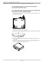
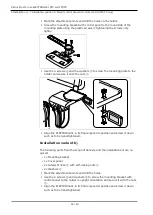
Page 40: ...ol unit and install it on the mounting bracket To detach the control panel from the control unit unscrew 2 screws on the underside of the device Pull the control panel off the control unit Break out one of the 4 cable feed throughs on the inside of the cover panel Guide the connecting cable of the control unit through this opening to the control panel Hold the cover panel to the position of the co...

Page 41: ...unit through this opening to the control panel Use 2 plastic screws to screw the control panel to the mounting bracket such as to be hand tightened Define the position for the control unit and check the length of the standard telephone cable Mount the control unit See also 2 4 4 Installation position 1 Mount below a holder Page 34 The following chapters describe the installation of the control pan...

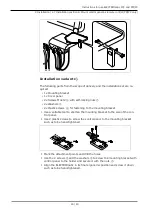
Page 42: ...personnel only Have the treatment center subjected to a safety check after installation The following parts from the scope of delivery and the installation set are re quired 1x Insert holder 1x Mounting bracket 1x Cover panel 4x 2x Screws M4x12 with self locking nuts 4x 2x Washers Optional 4x Spacer bolts 35 mm Optional 1x Mounting plate 2x Plastic screws Define the position of the control panel o...

Page 43: ...fe function and cause injury Have installations involving an intervention on the dental unit performed by trained expert personnel only Have the treatment center subjected to a safety check after installation Installation variant a The following parts from the scope of delivery and the installation set are re quired 1x Mounting plate 1x Mounting bracket 1x Cover panel 4x Screws M4x12 with self loc...

Page 44: ...holder and secure it with the nuts Align the ELECTROmatic in its final ergonomic position and screw it down such as to be hand tightened Installation variant b The following parts from the scope of delivery and the installation set are re quired 1x Mounting bracket 1x Cover panel 2x Screws M4x12 with self locking nuts 2x Washers Mark the attachment points and drill the holes Use the 2 screws and w...

Page 45: ...ashers 2x Plastic screws for fastening to the mounting bracket Use a suitable tool to shorten the mounting bracket to the size of the con trol panel Use 2 plastic screws to screw the control panel to the mounting bracket such as to be hand tightened Mark the attachment points and drill the holes Use the 2 screws and the washers to screw the mounting bracket with control panel to the holder and sec...

Page 46: ... wall CAUTION Damage to the dentist element Installations involving an intervention on the dental unit might damage compo nents which can interfere with the safe function and cause injury Have installations involving an intervention on the dental unit performed by trained expert personnel only Have the treatment center subjected to a safety check after installation The following parts from the sco...

Page 47: ... per forations as screw positions Installation in a cabinet Use 2 plastic screws to screw the control panel to the cabinet Installation on the wall Use 2 screws and washers to screw the mounting bracket with control panel to the wall and secure it with the nuts Mount the control unit See also 2 4 4 Installation position 1 Mount below a holder Page 34 4 8 Connect the ELECTROmatic See also 2 5 1 2 C...

Page 48: ... water is between 7 2 and 7 8 Note If the water is hard above 12 dH a water softening device based on an ion exchange procedure must be fitted Insufficient water hardness below 8 4 dH can promote the growth of al gae Note If necessary insert a filter water trap or air dryer Air and water requirements according to DIN EN 7494 2 The compressed air must be free of oil dirt and contamination If needed...

Page 49: ...he treatment unit to the filter of the ELECTROmatic or If the turbine hose of the treatment unit has a 2 hole or 3 hole connector replace the turbine hose with a 4 hole 5 hole or 6 hole turbine hose or use a commercial adapter available from specialized dealers See also 2 11 Accessories and consumables Page 73 5 1 3 Connecting the motor Slightly wet the O rings on the connection hose with KAVOspra...

Page 50: ...ICE Property damage from non approved power supply Property damage to the product Operate the product with the type 4882 power supply Mat no 1 005 0120 exclusively Note The connection of the power supply must comply with the country specific regulations and requirements for medical devices Note The power supply automatically adjusts to the available mains voltage Note Grounding reliability can onl...

Page 51: ... foot control Press the foot control down once as far as it will go maximum pressure in order to calibrate the foot control ð This starts up the motor and the system calibrates automatically to the ex isting system pressure Automatic calibration of the foot control The calibration is performed automatically during the first startup when the foot control is pressed for the first time Once the calib...

Page 52: ...otor Press the foot control to start the motor Adapt the system pressure of the treatment unit appropriately such that the cooling airflow is 6 to 9 Nl min upper edge of sphere Comply with the system pressure limits from the technical specifications for media See also 2 3 6 Technical specifications of the ELECTROmatic Page 25 5 4 Making the device settings Press both the plus and minus key for 2 s...

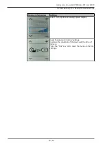
Page 53: ...antaneously Press both the plus key and the minus key for 2 seconds to exit from the Settings menu The following device settings can be changed according to need and or dis played when the device is being put into service Display information Setting Displays the software versions Turning SAFEdrive on off See also 2 6 6 Protection function SAFEdrive PM PC only Page 58 The LUX brightness can be adju...

Page 54: ...ndpiece can be adjusted between 0 and 9 sec onds 0 means that the LUX light does not after glow The volume of the key tone can be adjusted be tween 1 and 3 You can select from 3 different kinds of key tones Pressure display in psi and bar for checking the input pressure of the turbine hose Alignment of display The display can be aligned accordingly depending on its installation position ...

Page 55: ...4 Making the device settings Display information Setting Select from digital and analog speed display Reset the device to factory settings Restores the condition of the device at the time of delivery Press the Plus key 2x to reset the device to factory settings 55 80 ...

Page 56: ...t input values Check all input values on the display before use NOTICE Contaminated or moist compressed air at the compressed air connec tion Premature wear Supply dry clean and uncontaminated compressed air in accordance with ISO 7494 2 only Note Please note the transmission reduction ratio of the attachment handpieces as these have an impact on the displayed speed of the clamped tool 6 1 Switchi...

Page 57: ...own as far as it will go ð The set maximum speed is reached Press the foot control partly down in order to regulate the speed between minimum and maximum speed 6 3 Regulating the spray water CAUTION Hazard from insufficient amount of spray water Damage to the cog due to overheating Make sure that the motor speed is appropriate for the preparation on hand Use the requisite minimal amount of spray w...

Page 58: ... memo ries Speed memory INTRA LUX KL 703 LED min 1 rpm COMFORTdrive 200 XDR min 1 rpm 1 3 000 20 000 2 20 000 160 000 3 40 000 200 000 Press the 1 2 or 3 key ð The display shows the set speed speed min 1 x 1 000 Press the Plus or Minus key to change the saved value ð The display shows the speed Press the 1 2 or 3 key for more than 3 seconds to save the value in the respective speed memory ð Speed ...

Page 59: ...f defective or poorly maintained handpieces thus minimizing the risk of burn injuries to the patient SAFEdrive function Possible defects can be detected by continuous monitoring of the idling proper ties of the handpiece during its use If the protective function is triggered the SAFEdrive initially reduces the motor speed and then stops the motor altogether if the excessive load persists Note SAFE...

Page 60: ...Edrive function With regard to handpieces from third party manufacturers KaVo recommends disabling the SAFEdrive function as the SAFEdrive protection function is effec tive only with high speed handpieces from KaVo See also 2 6 6 1 Turning SAFEdrive on off Page 59 If SAFEdrive is activated and the handpiece is overloaded the first stage SAFEdrive alert is activated The motor power is reduced can l...

Page 61: ...re than 10 seconds the stage SAFEdrive error is reached The motor is stopped automatically The SAFEdrive icon is red and flashes If you use a handpiece from a third party manufacturer deactivate SAFEdrive or use a high speed handpiece from KaVo If an automatic motor stop signals that the SAFEdrive error status is evi dent remove the handpiece from the mouth of the patient and proceed as follows Ca...

Page 62: ...ice 7 2 Disconnecting the ELECTROmatic from the treatment unit Disconnect the 4 hole 5 hole or 6 hole hose of the treatment unit from the filter or the adapter of the 2 hole to 4 hole connector of the ELECTROmatic 7 3 Unplugging the motor COMFORTdrive Unplug the plug of the motor cord from the connector on the device Make sure to grasp the plug as close to the device as possible Note Clean and dis...

Page 63: ... must be checked by the processing entity for efficacy and possible detrimental consequences 8 1 Cleaning Note Do not use solvents or aggressive chemicals 8 1 1 Preparation at the site of use Unplug the unit from the main power supply Decontaminate as close as possible to use Remove extensive soiling immediately after it occurs 8 1 2 Manual external cleaning Note Do not use scouring cleansers Make...

Page 64: ...n accordance with manufacturer specifications Note The unit must be disinfected manually only 8 2 1 Manual external disinfection Use a soft disposable cloth and an approved disinfectant for germ reduction by wiping down all visible surfaces of the unit foot control surfaces and connecting cables Make sure that all surfaces are fully wetted Let the disinfectant act for the prescribed time Dry the s...

Page 65: ...aging Not applicable 8 4 Sterilization Not applicable 8 5 Storage Processed products must be stored protected from bacteria to the extent pos sible and dust in a dry dark cool room Note Comply with the expiration date of the sterilized items 8 6 Service inspection and testing after processing Note It is essential to comply with the hygiene requirements sterility during the test after processing If...

Page 66: ...user 9 1 Changing the filter water inlet CAUTION Hazard from insufficient amount of spray water Insufficient spray water can cause the medical device to overheat and damage the tooth Check and or change the filter Check the spray water channels and clean the spray nozzles with the nozzle pin according to need KaVo recommends checking the filter every 3 months initially and to change the filter ins...

Page 67: ...t surfaces align with those of the mount Slide the lamp into the mount Place the sleeve on the motor and pull it up Note The KaVo Mini LED lamp is a semiconductor element and must be operated with direct current only The lamp must be inserted with the poles in the cor rect orientation for the lamp to work properly NOTICE LED lamp inserted in wrong position with wrong polarity Damage to or bending ...

Page 68: ...er ated with direct current To ensure proper function the LED needs to be in serted with the correct polarity NOTICE LED lamp inserted in wrong position with wrong polarity Damage to or bending of the contacts Make sure that position and polarity are correct The following may happen after you turn on the KaVo MULTI LED lamp Case 1 KaVo MULTI LED lamp is on Case 2 KaVo MULTI LED lamp is red or off ...

Page 69: ...Instructions for use ELECTROmatic M C and PM PC 9 Maintenance 9 4 Replacing the motor hose Dispose of the defective motor hose in appropriate manner 69 80 ...

Page 70: ...andpiece off and actuate the spray water in bursts rinsing process Filter insert is soiled Replace filter on water inlet See also 2 9 1 Changing the filter water inlet Page 66 Spray water on treat ment unit or foot con trol is closed Open the spray on the treatment unit If the error persists unscrew the turbine hose and check if there is any flow of water If there is no flow of water notify a serv...

Page 71: ...on Function If you use a handpiece from a third party man ufacturer deactivate SAFEdrive or use a high speed handpiece from KaVo If you use a high speed handpiece from KaVo relieve the handpiece of its load for at least 2 seconds i e lift it off the tooth As soon as the motor reaches maximum speed again and the SAFEdrive icon turns yellow continue working as usual making sure to use intermittent m...

Page 72: ...ut off during continuous operation of the motor Comply with defined operating mode Event E8 Saved data or settings have been reset to starting value Confirm message and check or correct the pro gram settings If error persists notify the service engineer Event E12 No connection to mo tor Check restore correct connection Replace the motor cord If error persists notify the service engineer Event E14 ...

Page 73: ...se 1750 1 011 7200 KL Motor hose 2200 1 011 5668 COMFORTdrive 200 XDR 1 007 3570 COMFORTbase 1750 1 011 7335 COMFORTbase 2200 1 011 7076 Mini LED for INTRA LUX KL 703 LED motor 1 007 8474 KaVo MULTI LED lamp for COMFORTbase 1 007 5372 O ring set 8 3x0 68 for INTRAmatic 0 200 6120 O ring set 4 7x0 7 for COMFORTbase coupling 1 005 0327 O ring 17x1 KL motor 1 003 5822 O ring 17x0 8 KL motor 1 003 565...

Page 74: ... CISPR 11 Class B The ELECTROmatic is suitable for use in all facilities including resi dential facilities and areas that are directly connected to a public supply mains that also supplies buildings used for residential pur poses Emission of harmonics according to IEC 61000 3 2 Class A The ELECTROmatic is suitable for use in all facilities including resi dential facilities and areas that are direc...

Page 75: ...ng to IEC 61000 4 5 1 kV push pull volt age 2 kV common mode voltage 1 kV push pull volt age 2 kV common mode voltage The quality of the supply voltage should correspond to that of a typical business or hospital envi ronment Voltage interruptions short term interrup tions and fluctuations of the supply voltage according to IEC 61000 4 11 0 0 5 cycles at 0º to 315º in 45º increments 0 1 cycle 70 25...

Page 76: ...150 kHz and 80 MHz are 6 765 MHz to 6 795 MHz 13 553 MHz to 13 567 MHz 26 957 MHz to 27 283 MHz and 40 66 MHz to 40 70 MHz b The compliance levels in the ISM frequency bands between 150 kHz and 80 MHz and in the frequency range from 80 MHz to 2 5 GHz are intended to re duce the probability of mobile handheld communications facilities causing inter ference when they are inadvertently introduced int...

Page 77: ...nd mobile HF telecom munication devices transmitters and the ELECTROmatic depending on the output of the communication device as indicated below The table shows the necessary safe distance depending on the transmission fre quency in m Rated power of the transmitter in W 150 kHz to 80 MHz d 1 17 P 80 MHz to 800 MHz d 0 35 P 800 MHz to 2 5 GHz d 0 70 P 0 01 0 12 0 04 0 07 0 1 0 37 0 11 0 22 1 1 17 0...

Page 78: ......

Page 79: ......

Page 80: ...1 012 6302 bd 20191007 02 en US ...

Reviews: