background image

Technician's instructions GENTLEpower LUX Contra-angle 25 LP - REF 1.001.2849
2 Disassembly | 2.1 Disassembly of the GENTLEpower LUX Angle Piece 25 LP

6 / 20

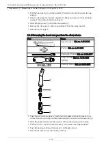
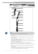
▶ Pull the head casing ① and the adapter ⑪ forward and out and remove the two

balls ⑨.

▶ Use the circlip pliers to twist the adapter ⑪ slightly and remove it from the head

casing ①, then remove the two springs ⑩.

▶ Slide the spray insert ③ out of the head casing ①.
▶ Remove the drive axle ⑤ and spring washer ④ from the spray insert ③.
▶ Remove two O-rings ②.

2.1.2 Removing the insert and gear from the elbow sleeve

Tool

Name
Assembly pliers (Mat. no. 0.411.3921)

Wrench (Mat. no. 0.411.1881)

Universal bit holder (Mat. no. 1.002.4577)
Torque handle (Mat. no. 1.003.1524)

180 Ncm

Clamping sleeve (Mat. no. 0.411.4451)

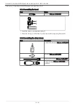
▶ Take hold of the elbow sleeve ① with the circlip pliers and turn the wrench, uni‐

versal bit holder and torque handle anticlockwise to unscrew the threaded ring ⑤.

▶ Slide the adapter sleeve into the insert ④ and push the spring pin into place.
▶ Pull the insert ④ out of the elbow sleeve ① and remove the adapter sleeve.
▶ Push the bearing cartridge ② and axle ③ right back and out.
▶ Remove the axle ③ from the bearing insert ②.


Summary of Contents for GENTLEpower LUX Contra-angle 25 LP

Page 1: ...Technician s instructions GENTLEpower LUX Contra angle 25 LP REF 1 001 2849...

Page 2: ...Distributed by KaVo Dental GmbH Bismarckring 39 D 88400 Biberach Phone 49 0 7351 56 0 Fax 49 0 7351 56 1488 Manufacturer Kaltenbach Voigt GmbH Bismarckring 39 D 88400 Biberach www kavo com...

Page 3: ...the axle 7 2 1 5 Disassembling the insert 8 2 1 6 Disassembling the elbow sleeve 8 3 Assembly 10 3 1 Assembly of the GENTLEpower LUX Angle Piece 25 LP 10 3 1 1 Assembly instructions 10 3 1 2 Assembli...

Page 4: ...tions TA TI Technician s instructions STK SC Safety checks IEC International Electrotechnical Commission RA RI Repair instructions EMV EMC Electromagnetic compatibility 1 1 2 Symbols Important informa...

Page 5: ...head Tool Description Ejector Mat no 1 001 3286 Wrench Mat no 1 001 3288 Universal bit holder Mat no 1 002 4577 Torque handle Mat no 1 002 4578 with 100 Ncm Circlip pliers Mat no 0 411 2421 Right Wro...

Page 6: ...emove two O rings 2 1 2 Removing the insert and gear from the elbow sleeve Tool Name Assembly pliers Mat no 0 411 3921 Wrench Mat no 0 411 1881 Universal bit holder Mat no 1 002 4577 Torque handle Mat...

Page 7: ...g and O ring 2 1 4 Disassembling the axle Tool Description Insert for spur gear assembly tool Mount for spur gear assembly tool Note The spur gear assembly tool Mat no 1 002 3898 comprises the insert...

Page 8: ...mbling the elbow sleeve Tool Name Puller Mat no 1 002 7470 Note Take care not to damage the fibre optic conductor when disassembling the elbow sleeve Use a hot air blower to heat up the glued joint on...

Page 9: ...ntra angle 25 LP REF 1 001 2849 2 Disassembly 2 1 Disassembly of the GENTLEpower LUX Angle Piece 25 LP Pull the fibre optic conductor spray pipe and spray pipe forward and out of the elbow sleeve Remo...

Page 10: ...piece has to be sprayed thoroughly with KAVOspray 3 1 2 Assembling the bearing cartridge Tool Name Mounting device A Mat no 1 002 3804 Mounting device B Mat no 1 002 3802 Apply a thin layer of grease...

Page 11: ...1 002 3898 comprises the insert the mount and the reducing shank Place the spring on the driver axle and push into the insert Push the reducing shank through the mount and attach the system bearing a...

Page 12: ...ling the insert Tool Name Wrench Mat no 1 002 0321 Insert the slide and pressure spring Place the O ring on the filter and screw in all the way using the wrench 3 1 5 Assembling the elbow sleeve Tool...

Page 13: ...o the bot tom of spray pipe Push the head casing into the conical sleeve to insert spray pipe and spray pipe into the head casing Insert the fibre optic bundle into the conical sleeve and slide over s...

Page 14: ...ove any residual adhesive from the end of the fibre optic bundle Place the angle piece in a hot air furnace and allow the adhesive to set for 30 mi nutes at 120 o C 3 1 6 Assembling the head Tool Desc...

Page 15: ...rt the two springs with their curvature upwards into the milled edges on the adapter Use the circlip pliers to slide the adapter into the head casing lining up the drilled holes for the balls at the s...

Page 16: ...hose Pressure gauge Mat no 1 003 1050 Motor 4 1 2 Test instruction Note The following evidence must be documented Customer s address and repair dates Material number or sales number of the product Ser...

Page 17: ...on Motor Connect the angle piece to the mo tor coupling and pull off The con nection should be made lock and disconnect with ease Check chuck Test drill Insert the test drill into the chuck and pull o...

Page 18: ...Measure the power consumption under test conditions with head and test drill Power consumption max 150 mA Check seals Leakage air hose Pressurize the media chamber with compressed air 2 bar and pressu...

Page 19: ......

Page 20: ...1 007 3086 bd 20160122 03 en...

Reviews: