background image

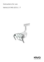
Instructions for use KaVoLUX 540 LED U / T

3 Product description | 3.1 Purpose – Proper use

▪ the unit was operated in accordance with the instructions for use, care and

installation.

▪ the IT components supplied by the operator meet the technical require-

ments in the present instruction for use for hardware and software, and are
installed and set up according to the descriptions of these components.

▪ in the case of repairs, the requirements of IEC 62353 "Recurrent tests and

tests before start-up of electrical items of medical electrical equipment and
systems - general regulations" are met in full.

It is a responsibility of the user:

▪ to only use equipment that is operating correctly,

▪ to protect him or herself, the patient and third parties from hazards, and

▪ to prevent contamination from the product

The applicable national legal regulations must be observed during the use of the
device, in particular the following:

▪ Applicable regulations governing the connection and startup of medical

devices.

▪ Current occupational safety regulations.

▪ Current accident prevention regulations.

Regular servicing and safety checks are essential for the permanent assurance
of the operating and functional safety of the KaVo product and for the preven-
tion of damage and hazards.
Testing and maintenance intervals: Maintenance must be performed once a
year, the safety checks at intervals of 2 years. Shorter intervals for the safety
checks may be specified by the tester if necessary.

The following persons are authorised to conduct repairs and servicing and the
safety check on the KaVo product:

▪ Technicians of KaVo branch offices after appropriate product training.

▪ Specifically KaVo-trained technicians of KaVo franchised dealers.

In Germany, operators, equipment managers and users are obliged to operate
their equipment in accordance with the MPG regulations.
The services encompass all the test tasks required in accordance with § 6 of the
medical devices operator ordinance (Medizinprodukte-Betreiberverordnung, MP-
BetreibV).

Note

The product must be cleaned and serviced according to instructions if it is not
to be used for an extended period of time.

Note

The treatment light may no longer be operated if the functional safety and
the faultless condition of the device cannot be guaranteed.

15 / 110

Summary of Contents for LUX 540 LED T

Page 1: ...Instructions for use KaVoLUX 540 LED U T...

Page 2: ...Distributed by KaVo Dental GmbH Bismarckring 39 D 88400 Biberach Phone 49 0 7351 56 0 Fax 49 0 7351 56 1488 Manufacturer Kaltenbach Voigt GmbH Bismarckring 39 D 88400 Biberach www kavo com...

Page 3: ...rpose Proper use 14 3 2 Operating light KaVoLUX 540 LED U 16 3 3 Operating light KaVoLUX 540 LED T 17 3 4 Dimensions and swing range 17 3 5 Rating plates 19 3 6 Technical data and requirements 20 3 7...

Page 4: ...4 6 2 Operation of the treatment light KaVoLUX 540 LED T 84 6 2 1 Turning the operating light On and Off 85 6 2 2 Setting the brightness 85 6 2 3 Changing between COMPOsave mode res dimmed light and n...

Page 5: ...y 105 10 3Guidelines and manufacturer s statement Electromagnetic immunity 106 10 4Recommended protective clearances between portable and mobile HF telecommunication devices and the KaVoLUX 540 LED 10...

Page 6: ...ssembly instructions TI Technician s instructions IEC International Electrotechnical Commission RI Repair instructions RK Retrofitting kit AS Assembly kit CK Conversion kit EP Enclosed parts EMC Elect...

Page 7: ...be held liable for defects and their consequences due to natural wear improper cleaning or servicing non compliance with operating servicing or connection instructions calcification or corrosion conta...

Page 8: ...tioned obligations will mean that the damage will be considered to have arisen following delivery in accordance with the General German Freight For warders Terms and Conditions Art 28 Outside Germany...

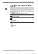
Page 9: ...se keep the packaging in case you need to return the product for servi cing or repair The symbols printed on the outside are for transportation and storage and have the following meaning Transport upr...

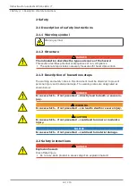
Page 10: ...n of hazardous steps The warning and safety notes in this document must be observed to prevent personal injury and material damage The warning notes are designated as shown below DANGER In cases which...

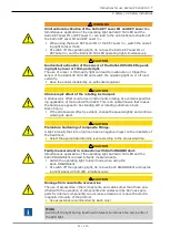
Page 11: ...KaVoLUX 540 LED This is an optical illusion that makes the handpiece appear to be standing still or rotating extremely slowly Risk of injury If the stroboscopic effect is evident change the speed slig...

Page 12: ...ed when the KaVoLUX 540 LED T is mounted to a treatment center The electrical installation must comply with the requirements and guidelines set down in VDE 0100 710 The safety checks must be done at 2...

Page 13: ...ceed as follows 1 On the homepage www enretec de of enretec GmbH you can download a form for a disposal order under the menu item eom Download the disposal order or complete it as an online order 2 En...

Page 14: ...n be mounted to the following treatment units ESTETICA E80 E80 Vision ESTETICA E70 E70 Vision ESTETICA E50 E50 Life The KaVoLUX 540 LED T can be mounted in the following positions to the fol lowing tr...

Page 15: ...accident prevention regulations Regular servicing and safety checks are essential for the permanent assurance of the operating and functional safety of the KaVo product and for the preven tion of dam...

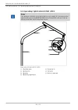
Page 16: ...UX 540 LED U Note The KaVoLUX 540 LED U operating light is only suitable for mounting to the KaVo treatment centre ESTETICA E80 E70 E50 and E50 Life as it can be directly controlled via the treatment...

Page 17: ...ESTETICA Standard 1063 ESTETICA E30 as well as for mounting to DSEclinical dental simulation units The assembly kit Mat no 07243401 is required for installation Components of the KaVoLUX 540 LED U Ope...

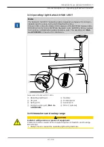
Page 18: ...oLUX 540 LED U T 3 Product description 3 4 Dimensions and swing range 18 110 843 659 120 240 300 Dimensions in mm 763 843 659 131 1 3 1 1 3 1 1 3 1 45 3 2 0 3 0 3 0 3 0 3 0 3 2 0 118 140 140 17 1 7 2...

Page 19: ...cture month serial number Supply voltage and power Reference number to product HIBC Code Type description VDE mark Disposal instructions see intended use eLabeling ID CE mark Read and take note of the...

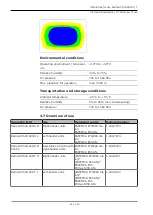
Page 20: ...th DIN VDE 0100 710 Free end at assembly point 1000 mm Customer provided fuse protection Automat C 16 or screw plug fuse 10 A Can be connected to the auto matic unit of the dental treatment centre Mai...

Page 21: ...e Operating light Use Treatment centre Material number KaVoLUX 540 LED U R Right hander units ESTETICA E70 E80 Vis ion ESTETICA E50 Life 1 008 7973 KaVoLUX 540 LED U L Left hander units ESTETICA E70 E...

Page 22: ...on for KaVo units or third party units 1 009 4273 KaVoLUX 540 LED T R L ceiling mounting Right hander left hander units for ceiling mount ing Device independent sup plement office configur ation for K...

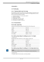
Page 23: ...6 Air pressure 700 hPa to 1060 hPa 4 1 2 Packed items For device assembly Packaged item Operating light with accessories and mounting pole Length 975 mm Width 545 mm Height 370 mm Gross weight approx...

Page 24: ...U T 4 Assembly 4 1 Packaging 24 110 Length 1 100 mm Width 600 mm Height 470 mm Gross weight approx 25 kg Net weight approx 18 kg 2 Stay bar Length 930 1300 mm Width 280 mm Height 230 mm Gross weight...

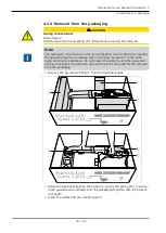
Page 25: ...ating light from damage when it is being removed from the pack aging and during installation Do not loosen the cable tie until the swivel arm has been installed The following sequence must be observed...

Page 26: ...the operating light into the mounting pole Do not loosen the cable tie until the swivel arm has been installed Do not remove the protective sheath until the swivel arm has been in stalled See also 2 4...

Page 27: ...protective earth conductor Take the anchor plate from the accessories and fix into place with the en closed screws Attach the cover and lock by turning clockwise 4 2 2 Requirements for mounting the d...

Page 28: ...r the ceiling mounting set and stay bar are automatically included in the delivery Note When noting the ceiling height in the order please indicate if the ceiling is suspended 4 3 Assembly of the KaVo...

Page 29: ...LED U Removing the rear service flap Remove the cover of the connection point Unscrew the cover Loosen screw below the main switch Loosen the fastening screws of the cladding see arrow and remove the...

Page 30: ...nto the mounting pole Insert the mounting pole into the lamp holder Positioning the mounting pole It is approx 1680 mm from the top edge to the floor The borehole for the swivel arm brake points in th...

Page 31: ...ough the lamp mounting pole Support arm with operating light and spring arm to be inserted in the lamp mounting pole from the top Screw in screw Mat no 10091123 to backstop The support arm must be abl...

Page 32: ...m the safety check according to the treatment centre Mount the device covers 4 3 2 ESTETICA E70 ESTETICA E80 WARNING Electrical power Death or injury from electric shock Before servicing pull the main...

Page 33: ...Instructions for use KaVoLUX 540 LED U T 4 Assembly 4 3 Assembly of the KaVoLUX 540 LED U Install the mounting pole 33 110...

Page 34: ...or the brake points to 6 o clock position 6 o clock position corresponds to the direc tion of the main switch of the unit Fix the mounting pole with locking screws and PE screw Guide the cover ring on...

Page 35: ...PCB Setting the CAN terminating resistance Note The CAN terminating resistances must be set correctly to ensure faultless functioning of the ESTETICA E70 and E80 The setting is dependent on the confi...

Page 36: ...S5 S5 SW1 S2 E80 SN 100xxxxx without 540 LED on off off off on n a with 540 LED off off off off on fix on E70 SN 200xxxxx without 540 LED n a on off off on n a with 540 LED n a off off off on fix on n...

Page 37: ...200 SW200 SW200 S2 E80 all SN with mot headrest off on off off on without mot headrest on on off off n a E70 all SN with mot headrest off on n a n a on without mot headrest on on n a n a n a not avail...

Page 38: ...U 38 110 Installing the light mounting pole Note The holder for the lamp mounting pole is not a top stop for the lamp mounting pole Note The lamp mounting pole must be adjusted together with the monit...

Page 39: ...ck position corresponds to the direc tion of the main switch of the unit Adjust the mounting pole to the corresponding height and fix with locking screws and PE screw Guide the cover ring on the unit...

Page 40: ...d plug into the slot on the central control PCB X12 1 Final tasks Mount caps on the swinging and spring arm Run function test Perform the safety check according to the treatment centre Mount the devic...

Page 41: ...Unit V2 3 0 Dentist V2 1 3 Display Dentist V2 3 0 E70 From 201xxxxx Unit V2 3 0 Dentist V1 5 0 E80 100xxxxx Unit V2 3 0 Dentist V2 1 3 Display Assist Dentist V2 3 0 E80 From 101xxxxx Unit V2 3 0 Denti...

Page 42: ...ntil U04 is shown on the display Press button S3 to raise the index to 9 Press the S5 button to set the note bit to 0 OP light LED is shown on the display Press and hold down button function level to...

Page 43: ...ed to make adjust ments in service mode Service tester Service tester I C Mat no 1 003 2212 See also 2 TA treatment unit Start continue and end the service mode To start service mode press and hold th...

Page 44: ...nue and end the service mode Press and hold down the Timer menu and Patient menu keys Press MEMOdent menu key briefly Press the Instrument menus button until U04 is shown on the display Function keys...

Page 45: ...t chair must be moved downwards to install the operating light Press button left and right on the foot control simultaneously and press down the cross switch to move the patient chair downwards 1 6 3...

Page 46: ...sembly of the KaVoLUX 540 LED T 46 110 Put the washer onto the lamp mounting pole 3 2 1 Thread the cover over the lamp mounting pole Connect the supply cable and protective conductor using the inserti...

Page 47: ...rating lamp into the lamp mounting pole Connect the protective conductor Connect supply lines to the terminals and pack in tubing as displayed Seal both ends of the tubing tightly with cable ties Pull...

Page 48: ...media opening of the lamp mounting pole 2 1 Then push the lines in small loops through the multimedia opening in the lamp mounting pole again Turn the swivel arm of the lamp until the threads appears...

Page 49: ...rform the safety check according to the treatment centre Mount the device covers 4 4 2 Primus 1058 WARNING Electrical power Death or injury from electric shock Before servicing pull the mains plug out...

Page 50: ...sembly of the KaVoLUX 540 LED T 50 110 Install the mounting pole Remove the unit covers 1 Loosen screws on the disinfection container and remove the container Ensure that the protective earth screw an...

Page 51: ...ntainer to its former position and fix with screws Align the body of the unit so that the mounting pole is exactly vertical see device installation instructions Check with a spirit level Push down the...

Page 52: ...ions of the treat ment centre The operating light is connected via the DCA relay Note ERGOcom light may not be connected to the DCA relay X28 if this connec tion is possible ERGOcom light will be dama...

Page 53: ...Instructions for use KaVoLUX 540 LED U T 4 Assembly 4 4 Assembly of the KaVoLUX 540 LED T 1 2 3 6 5 4 X28 KaVoLUX 540 LED T KaVoLUX 540 LED T 53 110...

Page 54: ...ARNING Electrical power Death or injury from electric shock Before servicing pull the mains plug out of the socket or completely discon nect the device from the power to de energise it After conversio...

Page 55: ...ED U T 4 Assembly 4 4 Assembly of the KaVoLUX 540 LED T Lift the hood and take it off towards the front 1 2 3 Unscrew the screws Dismantle the side panels 2 1 Loosen screws on the disinfection contain...

Page 56: ...nto the mounting pole Insert the mounting pole into the lamp holder Positioning the mounting pole It is approx 1680 mm from the top edge to the floor The borehole for the swivel arm brake points in th...

Page 57: ...he lamp mounting pole Support arm with operating light and spring arm to be inserted in the lamp mounting pole from the top Screw in screw Mat no 10091123 to backstop The support arm must be able to r...

Page 58: ...4 ESTETICA Standard 1063 Comfort 1065 Sensus 1066 WARNING Electrical power Death or injury from electric shock Before servicing pull the mains plug out of the socket or completely discon nect the dev...

Page 59: ...ESTETICA Standard 1063 Comfort 1065 Sensus 1066 the lamp support Mat no 07404711 is not mounted as a standard and must be fitted subsequently Insert the lamp support Mat no 07404711 into the support f...

Page 60: ...Positioning the mounting pole It is approx 1680 mm from the top edge to the floor The borehole for the swivel arm brake points in the direction 6 o clock Fix the mounting rod with the clamping screw...

Page 61: ...fety check according to the treatment centre Mount the device covers 4 4 5 Globus 1078 S Status 1080 TM C WARNING Electrical power Death or injury from electric shock Before servicing pull the mains p...

Page 62: ...or The borehole for the swivel arm brake points in the direction 6 o clock Tighten the protective conductor screw and fixing screws Align the mounting pole see unit installation instructions so that i...

Page 63: ...mbly 4 4 Assembly of the KaVoLUX 540 LED T Contact 2 blue wire Black wire is free X14 Final tasks Mount caps on the swinging and spring arm Run function test Perform the safety check according to the...

Page 64: ...Install the stay bar Connecting the lines Affix the covers Mount the ceiling adapter Determine the location on the ceiling for attachment according to installa tion plan Mat no 3 000 2059 included in...

Page 65: ...s and nuts on the thread of the back of the anchor 2 3 4 Screw the nuts tight so that the anchors grip the masonry Remove the nuts and washers Position the adapter base plate in such a way that the ar...

Page 66: ...tay bar to the correct length see installation plan Mat no 3 000 2059 Guide the large cover over the stay bar Turn the brass ring of the stay bar in a clockwise direction Position the swivel arm on th...

Page 67: ...Instructions for use KaVoLUX 540 LED U T 4 Assembly 4 5 Ceiling assembly of the KaVoLUX 540 LED T 5 6 7 1 2 3 4 67 110...

Page 68: ...and mains cable through the borehole and through the stay bar until only the five core end of the mains cable is protruding from the borehole 8 9 Connect the protective conductor of the mains cable an...

Page 69: ...x with screws Mat no 0 261 5031 and plate nut Mat no 1 004 5511 Insert the litz wires according to the connection diagram on the back of the switch Line No Switch No 1 1 1A 1A 2 2 2A 2A Carefully snap...

Page 70: ...w and tighten all the hex head nuts Adjust the nuts on the grub screws in the ceiling adapter so that the stay bar is suspended exactly perpendicular with the floor use a spirit level Connecting the l...

Page 71: ...ng light to the terminal U KaVoLUX 540 the polarity is irrelevant Roll up excess lengths of the lines and clamp them with a cable tie Affix the covers Note When the ceilings are covered use cover Mat...

Page 72: ...o position and lock the small cover with the three stud bolts 4 6 Centro mounting of the KaVoLUX 540 LED To be able to mount the KaVoLUX 540 LED on the Centro stand the routing of the lines in the swi...

Page 73: ...LED Remove the 4 Phillips head screws and pull the aluminium insert out of the swivel arm Route the lines over the aluminium insert and pass them through the hole downwards Remount the aluminium inse...

Page 74: ...e with which the swinging arm rotates Rotate the swinging arm until the screw is visible under the hole Tighten the screw to make it more difficult to rotate the swinging arm or loosen it to make it e...

Page 75: ...set using different brakes 5 3 1 Setting the rotary motion und 3D joint movement Note The cover must be removed to set the rotary motion and the 3D tilting The cover is fastened with a snap lock and...

Page 76: ...using two brakes Brake is for the presetting and needn t be adjusted in normal cases To set the brake the cover must be removed The cover is fastened with a snap lock and can be removed without tools...

Page 77: ...Mechanical settings 5 3 Setting the light head brakes Fine adjustment Pivot the light head upwards until the orifice in the cover of the cross slot adjustment screw is visible Carry out the precision...

Page 78: ...field at patients users or and third parties while you switch on the light Do not direct the light field at the patient s eyes when you move the light head Maintain a clearance of approx 700 mm betwee...

Page 79: ...amp functions according to a dimmed halogen lamp The colour temperature is approx 4 000 K and the composite can harden prematurely This can have a negative impact on the durability of the treatment Th...

Page 80: ...light key Press and hold down the Treatment light key Signal buzzes brightness changes from dark to bright in stages When the desired brightness is reached release the Treatment light key 6 1 3 Changi...

Page 81: ...ing prematurely As opposed to the dimmed light the blue components of the light are filtered in the process Therefore the composite can be processed longer in COMPOsave mode Note Use the Dim operating...

Page 82: ...on 6 1 6 Set colour temperature Note The colour temperature of the treatment light KaVoLUX 540 LED U can be set between five stages with the X ray viewer button in operating mode Treat ment lamp on Th...

Page 83: ...multaneously on the dentist element of the treatment unit The laser mode switches on Laser mode is activated the operating light shines for 1 second in green and then changes to a white light The indi...

Page 84: ...be rotated 45 to the left or 45 to the right Turn the switching ring to the right and it will spring back to its original pos ition If the treatment light is turned to the centre position zero positi...

Page 85: ...VoLUX 540 LED Press the operating light button or Hold your hand just in front of the sensor Treatment light is switched on Press the operating light button once again or Hold your hand just in front...

Page 86: ...ons according to a dimmed halogen lamp The colour temperature is approx 4 000 K and the composite can harden prematurely This can have a negative impact on the durability of the treatment The COMPOsav...

Page 87: ...radiation in tensity Press and hold down the Dim operating light button Brightness is increased in five stages Release the Dim operating light button when the desired brightness is achieved 6 2 6 Set...

Page 88: ...the KaVo KEY Laser III the KEY Laser 3 or the KaVo DIAGNOdent Sensor KaVoLUX 540 LED Press the operating light button and the operating light dimming button on the operating light simultaneously The...

Page 89: ...he switching ring to the left until it snaps into place Treatment light can be rotated 45 to the left or 45 to the right Turn the switching ring to the right and it will spring back to its original po...

Page 90: ...as cooled down CAUTION Damage to product as a result of improper cleaning Malfunctions unclean surfaces and risk of infection for operator and patients When using detergents adhere to the manufacturer...

Page 91: ...o 10024489 with a disinfectant wipe or thermodisinfection slight discolouration possible Approved disinfectants Incidin Liquid Ecolab FD 322 D rr Microcide AF Liquid Sch lke Mayr Use disinfectants in...

Page 92: ...te This chapter describes the safety check performed on the KaVoLUX 540 LED T for the case of ceiling mounting 8 2 1 Introduction General instructions Note The safety check may only be carried out by...

Page 93: ...ntained in the instructions for use must be adhered to in all products to be tested and inspected Note KaVo offers a medical device book for keeping an inventory and recording es sential master data o...

Page 94: ...e are interconnected via data lines or otherwise e g via electrically conductive attachments or coolant tubes the earth wire resistance of every single device must be checked Note If it should be impo...

Page 95: ...asuring processes The measured values may not over shoot the specified values Note Comparisons with previous measurements must be carried out if the meas ured values undershoot the threshold values by...

Page 96: ...irregularities determined in the visual inspection must be recorded in the test protocol It is essential to determine whether defects and deficiencies could have an adverse impact on the safe operati...

Page 97: ...rth connections could lead to erroneous measurements Note Cables and wires e g power supply cords measuring circuits and data lines must be arranged appropriately such that their influence on measurem...

Page 98: ...tor X2 of the measuring line Mat no 0 411 8811 Plug the second connector X2 of the KaVo measuring line into the mains plate X2 Insert the protective contact plug of the KaVo measuring cable into the s...

Page 99: ...e they leave the factory and included in the test Measuring the protective conductor resistance Limit 0 3 maximum value Note The integrity of the power supply cable in particular the protective earth...

Page 100: ...tions 8 2 Ceiling mounting 100 110 Protective earth measurement Scan the ceiling adapter of the treatment light with the probe 2 3 Base plate for the ceiling adapter Surroundings of the protective con...

Page 101: ...Protection class 1 WARNING Electrical power Death or injury from electric shock Conduct test for leakage current in devices of Protection Class 1 only after the protective earth test has been passed W...

Page 102: ...g results of functional tests Measuring test equipment including SN test equipment number and cal ibration period Final evaluation Name date and signature of test engineer There is a copy of a test re...

Page 103: ...aVoLUX 540 LED U T 8 Safety check Test instructions 8 2 Ceiling mounting 8 2 3 Test protocol for the safety check Unit leakage current replacement measurement Leakage current of applied part replaceme...

Page 104: ...cked by an authorised technician Operating light can no longer be operated via the control panel of the treatment centre Defective As an alternative operate the operating light via sensor or control b...

Page 105: ...540 LED is suitable for use in all equipment including devices in living areas and suit able for equipment which is dir ectly connected to a public power supply that also supplies build ings used for...

Page 106: ...ital en vironment Voltage interruptions short term interruptions and fluctuations of the supply voltage according to IEC 61000 4 11 5 V 95 inter ruption of the V T for period 40 V 60 drop in V T for 5...

Page 107: ...te check e d Disturbance is possible in the ambience of devices that exhibit the following icons Comment 1 At 80 MHz and 800 MHz the higher frequency range applies Comment 2 These guidelines may not b...

Page 108: ...f the KaVoLUX 540 LED can help to prevent electromagnetic interference by maintaining the minimum clearance between portable and mobile HF telecom munication devices transmitters and the KaVoLUX 540 L...

Page 109: ......

Page 110: ...1 008 8651 Fk 20190603 12 en...

Reviews: