Instructions for use KaVoLUX 540 LED U / T
4 Assembly | 4.5 Ceiling assembly of the KaVoLUX 540 LED T
70 / 110
6
7
4
1
2
8
3
5
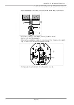
▶
With the stay bar
⑥
rotate the immediate plate
⑤
to the end of the slots so
that the two arrows on the intermediate pate and ceiling adapter point in
the same direction.
▶
Place the hex-head screw
⑦
on the grub screw
②
and tighten all the hex-
head nuts.
▶
Adjust the nuts on the grub screws in the ceiling adapter so that the stay
bar is suspended exactly perpendicular with the floor (use a spirit level).
Connecting the lines
Note
Only a certified electrician may install the electrical system.
Follow the provisions set down in VDE 0100-710 for the electrical installation.
Note
It must be ensured that the mains cable provided by the customer does not
cross other lines.
Affix with cable ties.
▶
Connect the customer mains cable to the terminal (L, N, PE).
Summary of Contents for LUX 540 LED U
Page 1: ...Instructions for use KaVoLUX 540 LED U T ...
Page 109: ......
Page 110: ...1 008 8651 Fk 20190603 12 en ...


