1. General Information
ORTHOPANTOMOGAPH OP 2D
7
Beam alignment test
Check the beam alignment. Refer to the Installation
manual of the unit for information on how to do this.
Ground test
Disconnect the unit from the main power supply before
carrying out this test.
For ME EQUIPMENT with an APPLIANCE INLET the
impedance between the earth pin in the APPLIANCE
INLET and any part that is PROTECTIVELY EARTHED
shall not exceed 0.1 ohm. The grounding resistance is
measured between APPLIANCE INLET ground pin and
any metal part of the unit.
The resistance MUST be <0.1 ohm.
Motor movements
Switch the unit off and then manually rotate the rotating
unit to check that the stepper motor moves freely and
without any looseness.
Switch the unit on, activate the T-mode "test" and then
take an exposure to check that the motors operate
smoothly and without any excessive noise.
Press the up/down keys to check the Z-motor (vertical
carriage movement). The motor must operate smoothly
and without any excessive noise.
Position detectors
Press the up key and drive the unit up. Make sure that
the unit stops moving at its uppermost position.
Press the down key and drive the unit down. Make sure
that the unit stops moving at its lowermost position.
Manually rotate the rotating unit to one of its end posi-
tions and then press the return button and make sure
that the rotating unit returns to the ready position. Re-
peat the test for the other end position.
Use service command
optotest
, see section 5.2 Ser-
vice Commands, to check the rotating unit optosensors.
Manually turn the rotating unit in one direction and then
press return. Repeat for the other direction.
Summary of Contents for ORTHOPANTOMOGAPH OP 2D
Page 2: ......
Page 4: ...IV ORTHOPANTOMOGAPH OP 2D Contents...
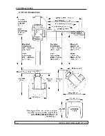
Page 24: ...14 ORTHOPANTOMOGAPH OP 2D 2 Unit Description 2 3 Unit dimensions...
Page 32: ...22 ORTHOPANTOMOGAPH OP 2D 2 Unit Description...
Page 33: ...2 Unit Description ORTHOPANTOMOGAPH OP 2D 23 2 6 Block diagram...
Page 34: ...24 ORTHOPANTOMOGAPH OP 2D 2 Unit Description 2 7 Fuse diagram...
Page 38: ...28 ORTHOPANTOMOGAPH OP 2D 2 Unit Description...
Page 43: ...3 Circuit Boards L1200 ORTHOPANTOMOGAPH OP 2D 33 L1200 Block Diagram...
Page 46: ...36 ORTHOPANTOMOGAPH OP 2D 3 Circuit Boards L1500 L1500 Block diagram...
Page 50: ...40 ORTHOPANTOMOGAPH OP 2D 3 Circuit Board L1600 L1600 Block diagram...
Page 54: ...44 ORTHOPANTOMOGAPH OP 2D 3 Circuit Boards L1700 L1700 Block Diagram...
Page 57: ...3 Circuit Boards L1800 ORTHOPANTOMOGAPH OP 2D 47 L1800 Block diagram...
Page 61: ...3 Circuit Boards P1910 ORTHOPANTOMOGAPH OP 2D 51 P1910 Block diagram...

