10
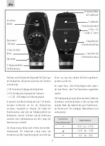
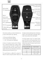
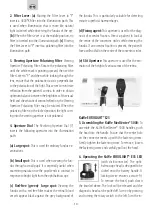
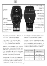
2. Filter Lever: (a)
Moving the Filter Lever to “F”
inserts a 4000°K filter into the illumination path. This
is used when illumination that is more like natural
light is desired while observing the fundus of the eye.
(b)
When the Filter Lever is at the middle position, no
filter is inserted into the illumination path.
(c)
Moving
the Filter Lever to “P” inserts a polarizing filter into the
illumination path.
3. Viewing Aperture Polarizing Filter
: Viewing
Aperture Polarizing Filter: Rotate the polarizing filter
until the white mark is pointing upward, then set the
Filter Lever to “P” and then while looking through the
lens, ensure that the polarization axis is perpendicular
to the polarization of the light. This serves to minimize
reflection from the patient’s cornea. In order to obtain
optimum balance between the brightness of the visual
field and the amount of corneal reflection, the Viewing
Aperture Polarizing Filter may be rotated. When the
polarizing filter is in the locked position, the light com-
ing into the viewing aperture is not polarized.
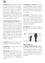
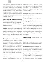
4. Aperture Dial
: The Revolving Aperture Dial (7)
inserts the following apertures into the illumination
path:
(a) Large spot:
This is used for ordinary fundus ex-
aminations.
(b) Small spot:
This is used when viewing the fun-
dus through a small pupil. It is especially useful when
examining macula since the pupil tends to contract in
response to bright light from the ophthalmoscope.
(c) Red-free (green)- large spot:
Viewing the
fundus with a red free filter makes the retinal blood
vessels appear black against the grey background of
the fundus. This is particularly valuable for detecting
minute superficial haemorrhages.
(d) Fixing agent:
This aperture is used for the diag-
nosis of eccentric fixation. Direct a patient to look at
the centre of the concentric circles while viewing the
fundus. If an eccentric fixation is present, the patient’s
fovea will not fall on the centre of the concentric circles.
(e) Slit Aperture
: This aperture is used for the esti-
mation of the height of various areas of the retina.
KaWe EUROLIGHT® E25
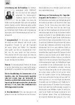
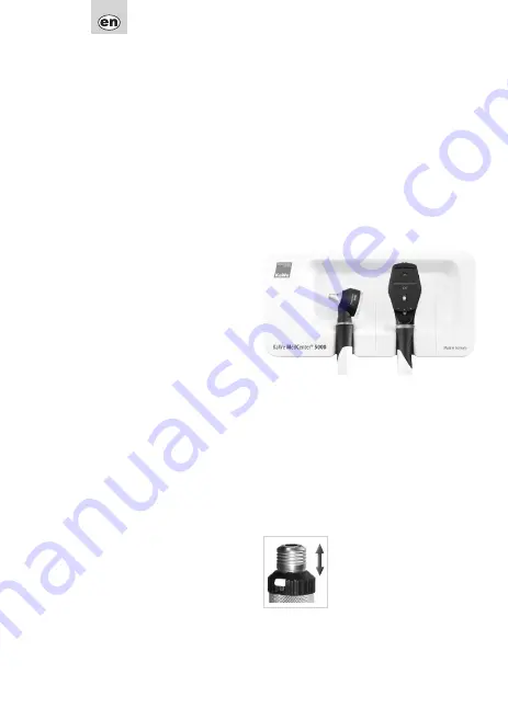
5. Assembling the KaWe MedCenter® 5000:
To
assemble the KaWe MedCenter® 5000 handles, push
the head into the handle. Ensure that the center hole
on the connector meets up with the fastening screw.
Gently tighten the fastening screw. To remove, loosen
the fastening screw and carefully pull out the head.
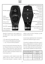
6. Operating the KaWe EUROLIGHT® E35 LED
(with click-connector): The opht-
halmoscope head is designed to be
clicked onto the battery handle. A
locking device ensures a secure fit.
To remove the head, push down
the knurled sleeve. The lock will be released and the
diagnostic head can be pulled off. Turn on by pressing
and turning the rotary switch to the left. Turn the in-


