background image

21

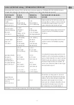
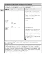
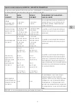
Guidelines and MANUFACTURER-Declaration – ELECTROMAGNETIC INTERFERENCE IMMUNITY

The KaWe MedCenter® 5000 is designed to be used in the types of ELECTROMAGNETIC ENVIRONMENTS listed below.  
The customer or user N15) is responsible for ensuring that this device is used in such an environment.

IMMUNITY TEST

IEC 60601-TEST 
LEVEL

CONFORMITY 
LEVEL

ELECTROMAGNETIC ENVIRONMENT –  
GUIDELINES

Conducted HF-
interference
according to  
IEC 61000-4-6

HF-interference 
according to
IEC 61000-4-3

3 V rms
150 kHz to 80 MHz

3 V/m
80 MHz to 2.5 GHz

3 V rms

3 V/m

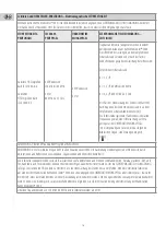
Portable and mobile HF communications equipment should 
be used no closer to the KaWe MedCenter® 5000 (including 
its power cords) than the recommended separation distance. 
The separation distance is calculated using various equations 
depending on the transmission frequency.

Recommended separation distance:

d = 1.2 √P
 
 
d = 1.2 √P 80 MHz to 800 MHz

d = 2.3 √P 800 MHz to 2.5 GHz

“P” is the maximum output power rating of the transmitter  
in watts (W) according to the transmitter manufacturer. “d”  
is the recommended separation distance in meters (m).  
Field strengths from fixed transmitters, as determined by an 
electromagnetic survey of the site are less than the COMPLI-
ANCE LEVEL in each frequency range.
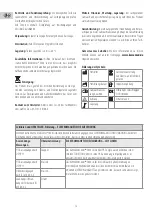
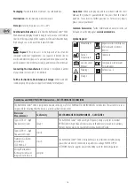
Interference may occur in the vicinity of equipment marked 
with the following symbol:


NOTE 1: For 80 MHz and 800 MHz, the larger of the two values applies.
NOTE 2: These guidelines may not apply in all situations. Electromagnetic propagation is affected by absorption and reflection from 
structures, objects and people.

Field strengths from fixed transmitters, such as base stations for radio (cellular/cordless) telephones and land mobile radios, amateur radio, 
AM and FM radio broadcast and TV broadcast cannot be predicted with accuracy in theory. It is recommended that in order to assess the 
ELECTROMAGNETIC ENVIRONMENT caused by fixed HF transmitters, an electromagnetic site survey should be conducted. If the measured 
field strength at the location at which the KaWe MedCenter® 5000 is used exceeds the applicable compliance level stated above, the equip-
ment should be checked at each of its locations of use in order to verify normal operation. If abnormal performance is observed, additional 
measures may be necessary, such as reorienting or relocating the KaWe MedCenter® 5000.
For frequencies ranging from 150 kHz to 80 MHz, the field strength is less than 3 V/m.

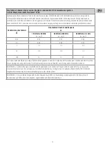
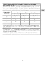
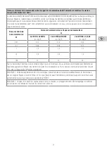
Recommended Separation Distances Between Portable and Mobile HF Communications Equipment and the
Wall Station KaWe MedCenter® 5000

The KaWe MedCenter® 5000 is intended for use in an ELECTROMAGNETIC ENVIRONMENT in which radiated HF disturbances are controlled. 
The customer or the user of the equipment can help prevent electromagnetic interference by ensuring that the minimum distance  
(shown below) between communications equipment (transmitters) and the KaWe MedCenter® 5000 is maintained. The minimum distance 
is dependent on the maximum output power and the frequency of the communications equipment. 

Rated Power Output of 

Transmitter (W)

Separation Distance According to Transmitter Frequencies (m)

150 kHz to 80 MHz

d = 1.2√P

150 kHz to 80 MHz

d = 1.2√P

150 kHz to 80 MHz

d = 2.3√P

0.01

0.12

0.12

0.23

0.1

0.38

0.38

0.73

1

1.2

1.2

2.3

10

3.8

3.8

7.3

100

12

12

23

For transmitters rated at a maximum output power not listed above, the recommended separation distance can be determined using the 
equation applicable to the frequency of the transmitter. P is the maximum output power rating of the transmitter in watts (W) according to 
the transmitter manufacturer.
NOTE 1: An additional factor of 10/3 is used in calculating the recommended separation distance for transmitters in the frequency bands 
between 80 MHz and 2.5 GHz in order to decrease the likelihood that mobile/portable communications equipment could cause interference 
if they are inadvertently brought into PATIENT areas. 
NOTE 2: These guidelines may not apply in all situations. Electromagnetic propagation is affected by absorption and reflection from 
structures, objects and people.
Summary of Contents for MedCenter 5000

Page 1: ...QM 1 195B KaWe MedCenter 5000 Gebrauchsanweisung User s Manual Mode d emploi Istruzioni per l uso Instrucciones de empleo Manual de opera o...

Page 2: ......

Page 3: ...nted Charging Station KaWe MedCenter 5000 16 Station murale KaWe MedCenter 5000 22 Stazione da parete KaWe MedCenter 5000 28 Estaci n de pared KaWe MedCenter 5000 34 Esta o de parede KaWe MedCenter 50...

Page 4: ...4...

Page 5: ...5...

Page 6: ...6...

Page 7: ...7...

Page 8: ...8...

Page 9: ...9...

Page 10: ...cken und festschrauben 9 Mit Schraubendreher und Schrauben R ckwandschale des Ab schlussrahmens fixieren 10 Frontschale des Abschlussrahmens aufstecken 11 Zur Demontage m ssen Sie die Wandstation vom...

Page 11: ...stauschteile Bei ersichtlichen Sch den ziehen Sie sofort den Netzstecker Das Netzteil dient als Trennvorrichtung und muss vom Netz getrennt werden wenn Sch den am Ger t ersichtlich sind Netzteil leich...

Page 12: ...Messungen bereinstimmung ELEKTROMAGNETISCHE UMGEBUNG LEITLINIEN HF Aussendungen nach CISPR 11 Gruppe 1 Das KaWe MedCenter 5000 verwendet HF Energie ausschlie lich zu seiner internen FUNKTION Daher ist...

Page 13: ...e 1kV Spannung Au enleiter Au enleiter 2kV Spannung Au enleiter Erde Die Qualit t derVersorgungsspannung sollte der einer typischen Gesch fts oder Krankenhausumgebung entsprechen Spannungseinbr che Ku...

Page 14: ...allen Frequenzen gem einer Untersuchung vor Ort a geringer als der BEREINSTIMMUNGSPEGEL In der Umgebung von Ger ten die das folgende Bildzeichen tragen sind St rungen m glich ANMERKUNG 1 Bei 80 MHz u...

Page 15: ...bis 800 MHz d 1 2 P 800 MHz bis 2 5 GHz d 2 3 P 0 01 0 12 0 12 0 23 0 1 0 38 0 38 0 73 1 1 2 1 2 2 3 10 3 8 3 8 7 3 100 12 12 23 F r Sender deren Nennleistung in obigerTabelle nicht angegeben ist kan...

Page 16: ...dule and frame to the base unit as de scribed in no 6 and secure it with screws 9 Use a screwdriver and screws to affix the rear panel of the frame to the wall 10 Attach the front panel of the frame 1...

Page 17: ...connect the power cord immediately The adapterservesinthiscaseastheseparatorandmustbedisconnected from the mains supply if damage is apparent The charging station is not designed for use in environmen...

Page 18: ...such an environment Emissions Measurement Conformity ELECTROMAGNETIC ENVIRONMENT GUIDELINES Type CISPR 11 high frequency emissions Group 1 The KaWe MedCenter 5000 uses high frequency energy solely for...

Page 19: ...to phase voltage 2kV phase to ground voltage 1kV phase to phase voltage 2kV phase to ground voltage The quality of the mains supply voltage should be the same as that of a typical commercial or hospit...

Page 20: ...ed transmitters as determined by an electromagnetic survey of the site are less than the COMPLI ANCE LEVEL in each frequency range Interference may occur in the vicinity of equipment marked with the f...

Page 21: ...2 P 150 kHz to 80 MHz d 1 2 P 150 kHz to 80 MHz d 2 3 P 0 01 0 12 0 12 0 23 0 1 0 38 0 38 0 73 1 1 2 1 2 2 3 10 3 8 3 8 7 3 100 12 12 23 For transmitters rated at a maximum output power not listed abo...

Page 22: ...ant la description de 6 et visser 9 l aide d un tournevis et des vis fixer la coque de la paroi arri re de l l ment final 10 Adapter la coque avant de l l ment final 11 La station murale doit tre d br...

Page 23: ...rer imm diatement la fiche de secteur Leblocd alimentationsertdedispositifded branchementet il doit tre d branch d s que des dommages sont constat s sur l appareil Utiliser un bloc d alimentation d ac...

Page 24: ...ns RF selon CISPR 11 Groupe 1 La station murale KaWe MedCenter 5000 utilise l nergie RF uniquement pour sa FONCTION interne Par cons quent ses missions RF sont tr s faibles et ne sont susceptibles de...

Page 25: ...ur 2 kV tension conducteur ext rieur terre La qualit du secteur lectrique doit tre identique celle d un environnement commercial ou hospitalier conventionnel Creux de tension coupures br ves et variat...

Page 26: ...ps produits par des transmetteurs RF fixes tablies par une tude lectromagn tique du site sont inf rieures au NIVEAU DE CONFORMIT de toutes les fr quences Des interf rences peuvent appara tre au voisin...

Page 27: ...z d 1 2 P de 80 MHz 800 MHz d 1 2 P de 800 MHz 2 5 GHz d 2 3 P 0 01 0 12 0 12 0 23 0 1 0 38 0 38 0 73 1 1 2 1 2 2 3 10 3 8 3 8 7 3 100 12 12 23 Pour les transmetteurs dont la puissance nominale ne fig...

Page 28: ...anciareedavvitarealmodulobaseilmodulodiampliamento e l elemento finale come descritto al punto 6 9 Fissarelaparteposterioredell elementofinaleservendosidivitie giravite 10 Applicare la parte frontale...

Page 29: ...ricambio In caso di danni evidenti staccare immediatamente la spina di rete L alimentatore funge da dispositivo di scollegamento e va staccato dalla rete di alimentazione quando si manifestano danni...

Page 30: ...n tale ambiente Misurazioni delle emissioni Concordanza Direttive per AMBIENTE ELETTROMAGNETICO Emissioni RF secondo CISPR 11 Gruppo 1 La stazione KaWe MedCenter 5000 utilizza energia RF esclusivament...

Page 31: ...re esterno massa 1kV tensione conduttore esterno conduttore esterno 2kV tensione conduttore esterno massa La qualit della corrente di alimentazione deve essere quella di un ambiente commerciale o ospe...

Page 32: ...e l intensit di campo di radiotrasmettitori fissi inferiore al LIVELLO DI CONCORDANZA in base ad una verifica sul luogo Disturbi sono possibili nei dintorni di apparecchiature che portano il simbolo s...

Page 33: ...MHz d 1 2 P da 800 MHz a 2 5 GHz d 2 3 P 0 01 0 12 0 12 0 23 0 1 0 38 0 38 0 73 1 1 2 1 2 2 3 10 3 8 3 8 7 3 100 12 12 23 Per trasmettitori la cui potenza nominale non indicata nella tabella sopra ri...

Page 34: ...el elemento final tal como se describe en el punto 6 sobre el m dulo b sico 9 Fijar con el destornillador y con los tornillos la parte posterior del elemento final 10 Colocar la parte frontal del elem...

Page 35: ...m ximo dos mangos para cada estaci n deparedKaWeMedCenter 5000 Elaparatonodisponederepuestos En caso de haber da os visibles desenchufe inmediatamente el dis positivo Lafuentedealimentaci nsirvecomod...

Page 36: ...arse de que se utiliza en un entorno de este tipo Prueba de emisiones Conformidad legal ENTORNO ELECTROMAGN TICO GU A Emisiones de RF seg n CISPR 11 Grupo 1 La estaci n de pared KaWe MedCenter 5000 s...

Page 37: ...uctor exterior 2 kV tensi n conductor exterior tierra La calidad de la red de energ a el ctrica debe ser equivalente a la existente en un comercio u hospital Ca da de tensi n interrupciones breves y v...

Page 38: ...como se determina en la evaluaci n electromag n tica del lugar debe ser inferior al NIVEL DE CUMPLIMIENTO en todas las frecuencias Pueden producirse interferencias en proximidad de equipos marcados c...

Page 39: ...Hz d 1 2 P de 80 MHz a 800 MHz d 1 2 P de 800 MHz a 2 5 GHz d 2 3 P 0 01 0 12 0 12 0 23 0 1 0 38 0 38 0 73 1 1 2 1 2 2 3 10 3 8 3 8 7 3 100 12 12 23 Para transmisores cuya potencia nominal no se enume...

Page 40: ...sico e fix los com os parafusos 9 Com a chave de parafusos e os parafusos fixar o estrutura do painel traseiro da caixa envolvente 10 Encaixar a estrutura frontal da caixa envolvente 11 Para desmontar...

Page 41: ...a KaWe MedCenter 5000 O aparelho n o disp e de pe as intercambi veis No caso de surgirem danos vis veis retire imediatamente a fonte de alimenta o A fonte de alimenta o de corrente serve de dispositiv...

Page 42: ...dade AMBIENTE ELECTROMAGN TICO ORIENTA ES Emiss es RF de acordo com CISPR 11 Grupo 1 Das KaWe MedCenterr 5000 utiliza energia RF apenas para o seu FUNCIONA MENTO INTERNO Por isso as suas emiss es de R...

Page 43: ...ns o fase terra A qualidade da corrente el ctrica deve ser equivalente de um ambiente hospitalar ou comercial t pico Quebras de tens o interrup es breves e flutua es da tens o de alimenta o de acordo...

Page 44: ...mo determinado por uma pesquisa no local electromagn tico deve ser inferior ao N VEL DE CONFORMIDADE Poder ocorrer interfer ncia na proximidade de equipa mento portador do seguinte s mbolo NOTA 1 A 80...

Page 45: ...m 150 kHz a 80 MHz d 1 2 P 80 MHz a 800 MHz 800 MHz a 2 5 GHz d 2 3 P 0 01 0 12 0 12 0 23 0 1 0 38 0 38 0 73 1 1 2 1 2 2 3 10 3 8 3 8 7 3 100 12 12 23 Para transmissores com uma pot ncia nominal n o i...

Page 46: ...46 KaWe M 5000 KaWe KaWe G 93 42 EWG 3 5 3 KaWe 5000 1 3 2 6 35 3 4 5 6 7 6 35 8 6 9 10 11 KaWe PICCOLIGHT 1 2 Stand by 3 4 5 KaWe KaWe PICCOLIGHT C...

Page 47: ...F O KaWe 5000 10 C 40 C 10 75 700 1060 hPa IP X0 II UE15WCP1 045200SPA 100 240V 50 60 Hz 4 5V DC 2 A 3 204 5 x 96 5 x 135 5 2800 700 810 80 x 96 5 x 135 5 2800 700 370 80x96 5x135 5 200 IEC 60601 1 1...

Page 48: ...48 5 60 C KaWe 5000 49 7141 68188 0 KaWe 5000 CISPR 11 1 KaWe 5000 CISPR 11 B KaWe 5000 IEC 61000 3 2 A IEC 61000 3 3 2 www kawemed de II...

Page 49: ...2 6 8 6 8 30 IEC 61000 4 4 2 1 2 1 IEC 61000 4 5 1 2 1 2 IEC 61000 4 11 5 UT 95 UT 0 5 40 UT 60 UT 5 70 UT 30 UT 25 5 UT 95 UT 5 5 UT 95 UT 0 5 40 UT 60 UT 5 70 UT 30 UT 25 5 UT 95 UT 5 KaWe 5000 50...

Page 50: ...50 KaWe 5000 KaWe 5000 IEC 60601 IEC 61000 4 6 IEC 61000 4 3 3 150 80 3 80 2 5 3 3 KaWe 5000 d 1 2 P d 1 2 P 80 800 d 2 3 P 800 2 5 P d 1 80 800 2 KaWe 5000 KaWe 5000 150 80 3...

Page 51: ...51 KaWe 5000 KaWe 5000 KaWe 5000 o 150 80 d 1 2 P o 80 800 d 1 2 P o 800 2 5 d 2 3 P 0 01 0 12 0 12 0 23 0 1 0 38 0 38 0 73 1 1 2 1 2 2 3 10 3 8 3 8 7 3 100 12 12 23 P 1 80 2 5 10 3 2...

Page 52: ...52...

Page 53: ...53...

Page 54: ...54...

Page 55: ...55...

Page 56: ...56...

Page 57: ...57...

Page 58: ...58...

Page 59: ......

Page 60: ...2 02 KIRCHNER WILHELM GmbH Co KG Eberhardstr 56 71679 Asperg Germany Zentrale Switchboard Fon 49 7141 68188 0 Fax 49 7141 68188 11 eMail info kawemed de Internet www kawemed de kompetenz in medizintec...

Reviews: