2 0 H a M e s i l a S t . , N e s h e r 3 6 8 8 5 2 0 , I s r a e l
P O B 2 5 0 0 4 , H a i f a 3 1 2 5 0 0 1 , I s r a e l
T e l : ( + 9 7 2 ) - 7 2 - 2 7 2 3 5 0 0 F a x : ( + 9 7 2 ) - 7 2 - 2 7 2 3 5 1 1
Page no. 47 | Appendix No. 1
9
Hardware Reference
9.1
Status LED
All SDI camera are equipped with a bi-color LED. Color coded indications are shown in the following table:
LED state
Indication
Fast flash green
Camera is connected, data is being transferred
Solid green
Camera is connected, no data being transferred or settings are being updated
Solid red
Internal error occurred / BIT failed
Table 4 – Connector indicator lamp states
9.2
Micro BNC Connector
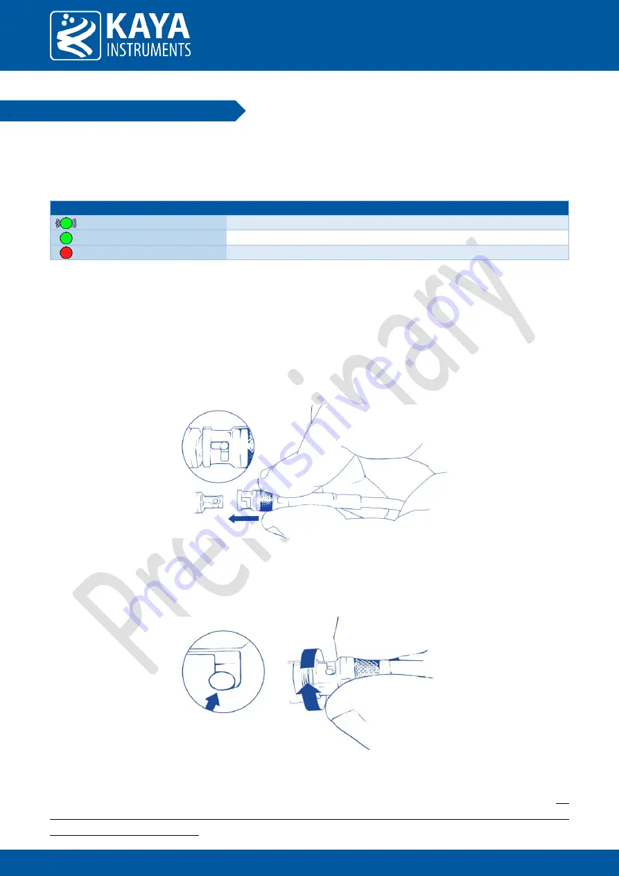
To connect the Micro-BNC cable, first need to align the pin on the male end with the “L” shaped track on the
female-connector of the Coaxial cable. Once aligned, the connector should be pushed in place (see figure no. 1).
Only mild pressure should be applied to achieve this operation, otherwise it may cause unnecessary damage to
the cable or the card.
Figure 6 – Pushing the Micro-BNC connector into place
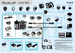
Once pushed all the way through, twist the connector clock-wise. The pin will move in the track locking the
connector in position:
Figure 7 – Twisting the connector and securing it in position
The cable can be removed by reversing the steps: twisting the connector counter-clock-wise and pulling it out. Do
not force the cable out! In case of resistance check for the pin location in relation to the track. Adjust as needed
and only then pull the cable out.


