High Speed Camera User Guide
19
KY-QSFP-CWDM – LC single mode, duplex cable, up to 10km connection over single mode
fiber cable
2.
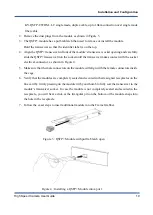
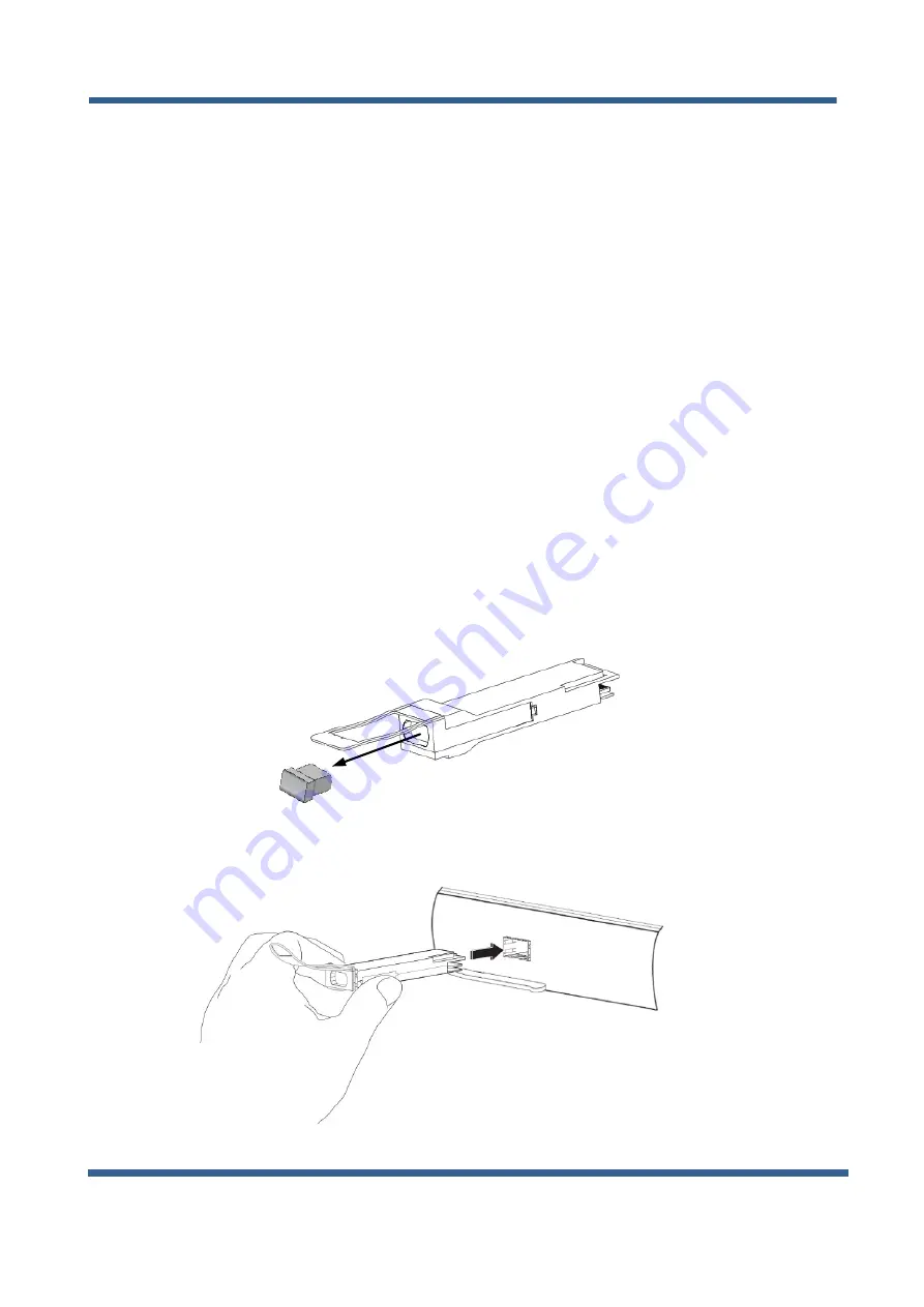
Remove the dust plugs from the module as shown in Figure 3.
3.
The QSFP+ module has a pull-tab latch that used to remove or install the module.
Hold the transceiver so that the identifier label is on the top.
4.
Align the QSFP+ transceiver in front of the module’s transceiver socket opening and carefully
slide the QSFP+ transceiver into the socket until the transceiver makes contact with the socket
electrical connector, as shown in Figure 4.
5.
Make sure that the male connectors on the module will align with the female connectors inside
the cage.
6.
Verify that the modules are completely seated and secured in their assigned receptacles on the
line card by firmly pressing on the module with your thumb to fully seat the transceiver in the
module’s transceiver socket. In case the module is not completely seated and secured in the
receptacle, you will hear a click as the triangular pin on the bottom of the module snaps into
the hole in the receptacle.
7.
Follow the exact steps to insert additional module into the Frame Grabber.
Figure 3 : QSFP+ Module with pull tab latch open
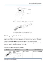
Figure 4 : Installing a QSFP+ Module into a port
Installation and Configurations


