background image

High Speed Camera User Guide 

21 


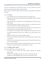
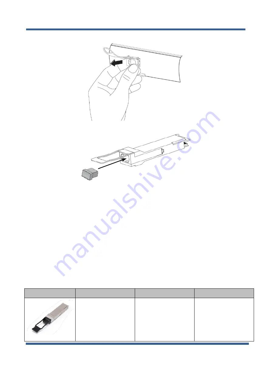
Figure 7 : Removing a QSFP+ Module from the port


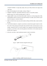
Figure 8 : QSFP+ Module with pull tab latch open


7.2.3


Completing the JetCam installation 

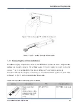
In  order  to  properly  complete  the  JetCam  system  installation,  connect  the  Power  Adaptor  to  the 

JetCam 

power  supply  connector.  The 

JetCam

  requires  12V  power  supply  for  proper  function  for 

camera. Please, refer 

section 8.1.2

 of this document for exact Power Supply requirements. 

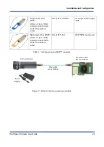
Turn the camera and the computer on and start your Vision Point software application. Please refer 

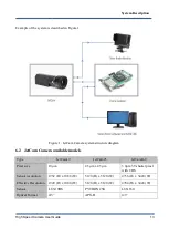
to Figure 9 for QSFP+ JetCam Camera connection example. 

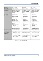
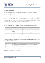
The system supports the following QSFP+ modules: 

Module 

Description 

P/N 

Compatible Cable


Single mode fiber 
QSFP+ 

Allows of up to 1.4km 
connection over single 
mode fiber cable (8 
cores) 

KY-QSFP-1.4 

MTP/MPO single mode 


Installation and Configurations 

Summary of Contents for JetCam Series

Page 1: ...eed Camera User Guide Part No KY JetCam 8 201 July 20 aMesila St Nesher 3688520 Israel P O B 2 50 0 4 Ha i fa 3 125 0 0 1 I s r a e l Tel 972 72 2723500 Fax 972 72 2723511 w w w k a y a i n s t r u m...

Page 2: ...2 Installation instructions 16 7 2 1 Komodo board installation 17 7 2 2 Installing and Removing QSFP Module 17 7 2 3 Completing the JetCam installation 21 8 Hardware Reference 23 8 1 JetCam unit Hardw...

Page 3: ...s 41 11 1 Device Control category 41 11 2 Image Format Control category 42 11 3 Acquisition Control category 43 11 4 ISP Features 44 11 5 Pixel Correction Control 44 11 6 Analog Control category 46 11...

Page 4: ...IGURE 15 GPIO CONNECTOR PIN OUT 27 FIGURE 16 JETCAM MECHANICAL DIMENSIONS 29 FIGURE 17 KOMODO BOARD LED S LOCATIONS 30 FIGURE 18 SERIAL COMMUNICATION EXAMPLE 34 FIGURE 19 FIRMWARE UPDATE EXECUTION 35...

Page 5: ...1 JETCAM CAMERA SYSTEM COMPONENTS 12 TABLE 2 JETCAM CAMERA MODELS 15 TABLE 3 JETCAM SUPPORTED QSFP MODULES 22 TABLE 4 SYSTEM STATUS LEDS BEHAVIOR 23 TABLE 5 QSFP SFP STATUS LEDS BEHAVIOR 24 TABLE 6 G...

Page 6: ...pin out 0 5 08 04 2018 Added QSFP installation instructions 0 6 24 04 2018 Updated power connector description 0 7 07 05 2018 Added image processing gain offset LUT Increased maximum frame rate Added...

Page 7: ...or electric shock may occur due to a short circuit or heat generation For inspection modification or repair contact our sales personnel Do not touch a cooling fan As a cooling fan rotates in high spe...

Page 8: ...ly damage the circuits In addition do not let your clothing come in contact with the circuit boards or components Otherwise the product may be damaged 4 2 Disclaimer This product should be used for ca...

Page 9: ...es arising from use of this product or damage of this product not due to our responsibility or failure due to modification Repair of this product is carried out by replacing it on a chargeable basis n...

Page 10: ...SDI output enables connection of local monitor as viewfinder or an installation aid 5 2 Areas of Application This camera is ideally suited for Aerospace Machine Vision Systems Industrial Machine Visio...

Page 11: ...rinting inspection High speed DVRs Defense remote systems Surveillance 5 5 Related documents and accessories Documents Vision Point Software Installation Guide Vision Point App User Guide for Acquisit...

Page 12: ...erface for distances up to 80km in single mode and up to 300m in multi mode Link supports standard up to 40 Gbps over fiber optic interface The JetCam system configuration includes the following parts...

Page 13: ...n Point Software and SDK Friendly Software environment includes Video management GUI SDK and API Table 1 JetCam Camera system components For more information about the system components please refer t...

Page 14: ...m Camera available models Type JetCam19 JetCam25 JetCam160 Pixel size 10 m 4 5 m x 4 5 m 3 9 m 5T shutter pixel with CDS Sensor resolution 1952 H x 1088 W 5120 H x 5120 W 4736 H x 3424 W Effective Res...

Page 15: ...e 14 e Non Zero ROT 1x gain TBD Parasitic Light Sensitivity PLS TBD 1 5000 TBD Full Well Charge 15000 e 12000 e TBD Dynamic range 56 9321 dB at 520 nm 54 6332 dB at 520 nm TBD Signal to Noise Ratio SN...

Page 16: ...ame counter Flat field correction LUT Gain Analog Digital Auto black level Nonvolatile storage Defect pixel correction White balance ROI Image flip Frame counter Flat field correction LUT Gain Analog...

Page 17: ...Application installation JetCam camera Komodo Fiber board Fiber QSFP Modules Fiber optic cable NOTE KAYA Instruments doesn t guarantee compatibility with all computers that have the above specificati...

Page 18: ...tter inside the PCIe slot and the Frame Grabbers PCIe connector or blocking any of the connectors 4 Firmly insert the Komodo board to PCIe connector of the motherboard 5 Anchor the PCIe bracket to the...

Page 19: ...ug until you are ready to attach the network interface cable 6 Do not install or remove the QSFP module with fiber optic cables attached to it because of the potential of damaging the cable the cable...

Page 20: ...ctor as shown in Figure 4 5 Make sure that the male connectors on the module will align with the female connectors inside the cage 6 Verify that the modules are completely seated and secured in their...

Page 21: ...nnecting the cable to QSFP Module Removing the QSFP Module In order to remove the QSFP module follow these steps 1 Turn the camera and the JetCam camera and the Frame Grabber off 2 Disconnect and remo...

Page 22: ...er supply for proper function for camera Please refer section 8 1 2 of this document for exact Power Supply requirements Turn the camera and the computer on and start your Vision Point software applic...

Page 23: ...LC single mode duplex cable Multi mode fiber QSFP Allows of up to 300m connection over multi mode fiber cable 8 cores KY QSFP 3M MTP MPO multi mode Table 3 JetCam supported QSFP modules Komodo Fiber F...

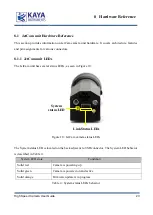
Page 24: ...nit has several status LEDs as seen in Figure 10 Link Status LEDs System status LED Figure 10 JetCam camera status LEDs The System status LED is located on the back adjacent to USB connector The Syste...

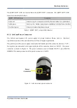
Page 25: ...vior 8 1 2 JetCam Power Connector The JetCam unit requires 12V power supply for proper function Please refer to Electrical specification section of this document for exact Power Supply requirements Th...

Page 26: ...I with a resolutions of 1080p60 Single link standard coaxial 75 ohm cable Streams serial digital video 10 bit YCrCb 4 2 2 encoding SDI Connector Figure 12 JetCam camera SDI connector NOTE Powering up...

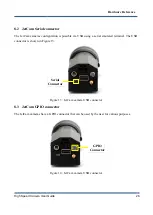
Page 27: ...ing a serial emulated terminal The USB connector is shown in Figure 13 Serial Connector Figure 13 JetCam camera USB connector 8 3 JetCam GPIO connector The JetCam cameras have a GPIO connector that ca...

Page 28: ...l communication can t be used for both at the same time 2 Used for external trigger as well as for the serial communication can t be used for both at the same time An HR 10 A 7 P 6 S Hirose Electric c...

Page 29: ...rts the following mount models Module Description Nikon F mount Three lug bayonet mount with a 44 mm throat and a flange to focal plane distance of 46 5 mm Canon EF mount Short flange focal distance o...

Page 30: ...9 8 5 Mechanical dimensions The exact device mechanical dimensions are as defined in Figure 16 For more detailed information please contact KAYA Instruments representative Figure 16 JetCam Mechanical...

Page 31: ...D LED 0 LED 1 LED 2 LED 3 QSFP CH 0 LED QSFP CH 1 LED QSFP CH 2 LED QSFP CH 3 LED Figure 17 Komodo Board LED s locations LED state Description Solid orange System is not initialized Slow pulse red No...

Page 32: ...receives clock from PCIe LED 1 PCIe L0 state When lit indicates that the PCIe interface is powered up at active state LED 2 Gen3 PCIe indicator When lit indicates that PCIe is working as Gen3 When no...

Page 33: ...PIO 9 3 Operating conditions Parameter Description Minimum Typical Maximum 12V Vcc 12V Supply voltage 11 04V 12V 12 96V 12 Icc Supply Current from 12V 2A Table 12 Operating conditions Symbol Parameter...

Page 34: ...r driver installation and USB connection is acquired a serial emulated terminal i e Tera Term use is recommended can be used with the following configurations described in Table 15 Parameter Value Bau...

Page 35: ...nd the camera and acquire connection using Silabs drivers drivers need to be downloaded manually if an automatic download isn t initiated 2 Open serial emulated terminal usage of Tera Term terminal is...

Page 36: ...the File tab use the terminal transfer capability using the XMODEM protocol to initiate the firmware update Choose Send and the firmware update file JetCam_XXX_YYY_ZZZ bin where XXX is the model name...

Page 37: ...JetCam The Vision Point Application allows to connect and configure the Frame Grabber and the connected JetCam camera The basic steps include 1 Selecting a grabber board 2 Opening creating and closing...

Page 38: ...Click Create new project to create new project from scratch or Open existing project to open an existing one The Vision Point App main window with all of its components as shown in Figure 24 1 2 4 3 F...

Page 39: ...on frame rate and image format can be found at the bottom of the picture window 4 The system messages window Displays general runtime informational and error messages regarding the state of stream gra...

Page 40: ...Control category located in the Camera tab 10 7 Buffer Replay Mode After the stream acquisition commenced controlling acquisition and replaying frames can be made using the picture window toolbar In o...

Page 41: ...er option This will open a save dialog where you should choose the destination folder and file name Click Save to save the currently captured video in the Picture Window For more detailed information...

Page 42: ...ollowing categories 11 1 Device Control category 1 2 3 4 5 6 7 8 9 Figure 26 Device Control category 1 Shows camera vendor JetCam model and manufacturer 2 Device serial number 3 Device Firmware shows...

Page 43: ...The Height and the width of the displayed image 5 Offset X Y 6 Pixel format 7 Scan type only Area Scan is available for now 8 Test Pattern has 6 available options Grey Vertical Ramp Gray Horizontal R...

Page 44: ...d by received trigger The exposure duration is set according to the exposure time parameter c Trigger Width timed exposure initiated by received trigger The exposure duration is set according to the w...

Page 45: ...a White balance Gain per color b Black level correction 4 LUT a Gamma correction b General purpose LUT per color The ISP will be per single fiber channel and will accept 4 pixels in parallel Each ISP...

Page 46: ...easured during the calibration stage This correction is valid for the specific camera settings and conditions gain exposure time temperature etc which were selected during the calibration process Foll...

Page 47: ...the selected defected pixel in steps of 1 range from 0 to the maximum height of the full frame minus 1 i e 1079 for JetCam19 5 Remove the selected defected pixel entry 6 Enable the Dark filed correcti...

Page 48: ...colors channels b Red color channel c Green color channel d Blue color channel 5 Digital Black Level in steps of 1 range from 1023 to 1023 6 Analog Black Level in steps of 1 256 range from 1 2 to 1 2...

Page 49: ...1 UserSet save camera configuration Three user sets are available for saving different camera parameter configurations In addition a Default UserSet is available so it will be possible to revert back...
Page 50: ...mera s non volatile memory 2 All data will be erased in 1 burst 3 Data can be saved in bursts of 256 bytes each time All 256 should be filled either with valid or padding data 4 If data is loaded befo...

Page 51: ...x30300 buffer bufferSize uint8_t buffer 256 0 1 2 3 uint32_t bufferSize sizeof buffer KYFG_CameraWriteReg camHandle 0x30300 buffer bufferSize 3 4 Figure 34 Non Volatile memory save function call seque...

Page 52: ...optical cross talk from neighboring pixels Green1 pixels are located on a green red row green2 pixels are located on a blue green row Figure 35 Color Filter Array for the Pixel Array Similarly the Jet...

Page 53: ...um Efficiency The following figures show the quantum efficiency of the JetCam 25 camera Figure 36 JetCam 25 Quantum Efficiency Curve for Mono and Color Figure 37 JetCam 25 Quantum Efficiency Curve for...

Page 54: ...User Guide 53 The following figures show the quantum efficiency of the JetCam 19 camera Figure 38 JetCam 19 Quantum Efficiency Curve for Mono Figure 39 JetCam 19 Quantum Efficiency Curve for Color Ad...

Page 55: ...distance communication links and for applications where high power must be transmitted Single mode fibers are used for most communication links longer than 300 meters 1 200 ft 13 2 Optional periphera...

Page 56: ...tup at camera side 9 Under Frame grabber Extended Stream Features Camera selector 0 Device Serial Port Control set the Serial Port Selector to PeripheralGPIO_0 Set the Serial Port Number to any non ze...

Page 57: ...ports to ignore you see JetCam X RS232 0 COM Y where X is the JetCam model and Y is the com port selected in the previous section 4e Do not select anything in this window and click on Cancel Figure 43...

Page 58: ...e KY QSFP 40G85 QSFP multi mode module KY QSFP SR4 40G QSFP CWDM single mode module KY QSFP 10 CWDM QSFP MTP MPO single mode Fiber cable X m KY FCA MTP SM QSFP MTP MPO multi mode Fiber cable X m KY FC...

Reviews: