High Speed Camera User Guide
24
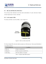
The QSFP+/SFP+ LED are located below the QSFP+\SFP+ connectors. The QSFP+/SFP+ LED
behavior is described in Table 5:
QSFP / SFP LED state
Condition
Solid red
Camera is up. No connection with the Frame Grabber was established
Solid green
Link is active. Stable connection is established with the Frame Grabber
Fast flash green
Camera is in data transmission mode
Table 5 : QSFP+/SFP+ status LEDs behavior
8.1.2
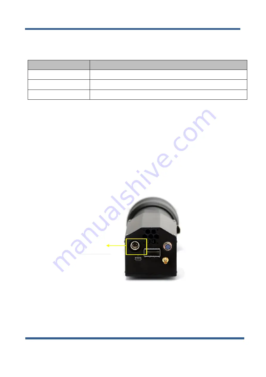
JetCam Power Connector
The JetCam unit requires 12V power supply for proper function. Please, refer to Electrical
specification section of this document for exact Power Supply requirements.
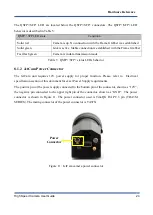
The positive pin of the power supply connected to the bottom pin of the connector, shown as “12V”,
the negative pin connected to the upper right pin of the connector, shown as “GND“. The power
connector is shown in Figure 11. The power connector used is Tini-QG RA PC 3 pin (TRA3M
SERIES). The mating connector of the power connector is TA3FX.
12V
Power
Connector
GND
NC
Figure 11 : JetCam camera power connector
Hardware Reference

