background image


Komodo II CoaXPress Frame Grabber 

Hardware Reference and Installation 

Guide


(Part-No. KY-FGKII)


December 2018 


2 0   a M e s i l a   S t . ,   N e s h e r   3 6 8 8 5 2 0 ,   I s r a e l  
P O B   2 5 0 0 4 ,   H a i f a   3 1 2 5 0 0 1 ,   I s r a e l  
T e l : ( + 9 7 2 ) - 7 2 - 2 7 2 3 5 0 0   F a x : ( + 9 7 2 ) - 7 2 - 2 7 2 3 5 1 1  
w w w . k a y a i n s t r u m e n t s . c o m  


Summary of Contents for Komodo CoaXPress II

Page 1: ...dware Reference and Installation Guide Part No KY FGKII December 2018 20 aMesila St Nesher 3688520 Israel P O B 2 5 0 0 4 H a i f a 3 1 2 5 0 0 1 I s r a e l Tel 972 72 2723500 Fax 972 72 2723511 w w...

Page 2: ...ternal View of the Board 10 Mechanical Specifications 11 5 1 Essentials to get started 11 5 2 Power supplies 11 5 3 Mechanical dimensions 13 Installation and Configurations 14 6 1 Installation instruc...

Page 3: ...GURE 9 LEVEL SHIFTERS SCHEMATIC 20 Tables TABLE 1 COAXPRESS LINKS STATUS LED S 15 TABLE 2 BOARD STATUS LED S 16 TABLE 3 GPIO CONNECTOR PINOUT 21 TABLE 4 ABSOLUTE MAXIMUM RATINGS 22 TABLE 5 ABSOLUTE MA...

Page 4: ...ot disassemble repair or modify the product Otherwise a fire or electric shock may occur due to a short circuit or heat generation For inspection modification or repair contact our sales personnel Do...

Page 5: ...s Improper handling can seriously damage the circuits In addition do not let your clothing come in contact with the circuit boards or components Otherwise the product may be damaged Disclaimer This pr...

Page 6: ...r other abnormalities arising from use of this product or damage of this product not due to our responsibility or failure due to modification Repair of this product is carried out by replacing it on a...

Page 7: ...also provides an external on bracket GPIO for machine control signals such as triggers shaft encoders exposure control and general I O which can be control aside video stream receive The Komodo II us...

Page 8: ...tes up to 12 5 Gbps per link PCI Express Transfer Rate of up to 50 Gbps 0 C to 55 C operating environment temperature Flexible machine I O 4 TTL configurable I Os 4 LVCMOS configurable I Os 2 LVDS inp...

Page 9: ...ts and accessories Documents Vision Point App User Manual Vision Point API Reference Book CoaXPress standard 2 0 KAYA Frame Grabbers Programming Guide Accessories CoaXPress cables Micro BNC to Micro B...

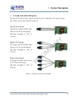
Page 10: ...mera Topology Single Dual or Quad CoaXPress links with up to 12 5 Gb per link topology Maximum throughput to PCIe of 55 Gb sec Quad Camera Topology Two Single or Dual CoaXPress links with up to 12 5 G...

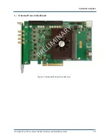
Page 11: ...Komodo II CoaXPress Frame Grabber Hardware and Installation Guide 10 External View of the Board Figure 2 Komodo II board external view System Description...

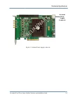
Page 12: ...mputers that have the above specifications Please consult KAYA representative for any specific issue Power supplies The Komodo II board receives its power directly from PCIe connector of the motherboa...

Page 13: ...Komodo II CoaXPress Frame Grabber Hardware and Installation Guide 12 External Power Supply Connector Figure 3 External Power supply connector Mechanical Specifications...

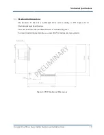
Page 14: ...II board is a half length PCIe card according to PCI Express Card Electromechanical Specification The exact board mechanical dimensions are as defined in Figure 4 For more detailed information please...

Page 15: ...o install a driver for new Multimedia Device At this stage you should cancel the installation Under Windows and Linux the compatible drivers for Komodo II board will be installed during installation o...

Page 16: ...nitialized Slow pulse red No camera is connected Fast flash alternate green orange Connection detection in progress PoCXP active Fast flash orange Connection detection in progress PoCXP not in use Sol...

Page 17: ...s clock from PCIe LED 1 PCIe L0 state When lit indicates that the PCIe interface is powered up at active state LED 2 Gen3 PCIe indicator When lit indicates that PCIe is working as Gen3 When not lit th...

Page 18: ...up to 55 Gbps DMA Equalizer Video stream channel Control channel Equalizer Video stream channel Control channel Equalizer Video stream channel Control channel Equalizer LED LED LED LED Micro BNC Exter...

Page 19: ...l and general I O which can be controlled aside the video stream acquisition The Komodo II board uses a standard HD DB26 D sub Panel Mount connector 26 pin 3 row through hole right angle The auxiliary...

Page 20: ...Komodo II CoaXPress Frame Grabber Hardware and Installation Guide 19 J 7 Figure 7 GPIO connectors location Installation and Configurations...

Page 21: ...IN0 GPIOE_OPTO_IN3 GPIO_OPTO_IN1 GPIO_OPTO_IN0 GPIO_OPTO_IN3 GPIO_OPTO_IN2 GPIO_LVDS_EN 1k 1k 1k 1k 91 91 91 91 1 1 2 2 3 3 4 4 5 5 6 6 7 7 8 8 9 9 10 10 11 11 12 12 13 13 14 14 15 15 16 16 17 17 18 1...

Page 22: ...ut Up to 70V Optically isolated outputs 11 OptoCoupled Output 2 Opto Isolated output Up to 70V Optically isolated outputs 12 OptoCoupled Output 3 Opto Isolated output Up to 70V Optically isolated outp...

Page 23: ...OptoCoupled Output 2 Opto Isolated output Up to 70V Optically isolated outputs 12 OptoCoupled Output 3 Opto Isolated output Up to 70V Optically isolated outputs 13 OptoCoupled Input 0 Opto Isolated i...

Page 24: ...0 5 6 5 LVTTL 0 5 6 5 Note The maximum current that the Opto isolated out IOs can support is 150mA Table 5 Absolute maximum ratings for GPIO Electrical characteristics for board IO s Electrical chara...

Page 25: ...hreshold 100 15 mV VCMR Common Mode Voltage Range VID 100 mV VDD 3 3 V 0 05 3 V IIN Input Current VDD 3 6 V VIN 0 V or 2 8 V 12 4 12 A VDD 0 V VIN 0 V or 2 8 V or 3 6 V 10 1 10 A Table 7 LVDS Input DC...

Page 26: ...L Input Low Voltage 0 1 5 V IIN Input Current VIN 0 V or VIN VDD 1 A Note Vdd 5V unless specified otherwise Table 10 TTL input specifications Symbol Parameter Test condition MIN MAX Units VOH Output H...

Reviews: