background image

ZHEJIANG KAYO MOTOR CO., LTD.


www.kayomoto.us


63 


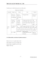
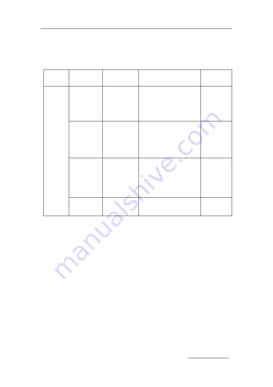
Troubleshooting of the cylinder body, please refer to the following table 

Maintenance of Cylinder Body   

Description 

Damage form 

Trouble 

Cause 

Correction 


Cylinder 

body 


Excessive oil 

dirt or sand on 

the radiating fins 


Poor heat 

radiation of the 

fins on cylinder 

body 

The engine overheats 

Remove the oil 

dirt or sand 

Cylinder end 

surface badly 

distorted 

Air leakage 

between the 

cylinder and 

cylinder head 

The  engine  starts  hard  or  fails  to 

start  .Insufficient  engine  output; 

poor  idle  speed  and  high  fuel 

consumption 

Grind 

the 

cylinder 

end 

surface 

or 

replace 

the 

cylinder body 

The cylinder is 

badly worn 

The 

fitting 

clearance  between 

the  cylinder  and 

position,  position 

ring is too wide 

The  engine  starts  hard  or  fails  to 

start  .Insufficient  engine  output; 

Poor  engine  idle  speed.  Thick 

blue  and  white  fume  form  the   

exhaust muffler pipe. 


Repair 

with 

boring  machine 

or  replace  the 

cylinder body. 


The 

cylinder 

gasket 

is damage 


Oil leakage between the cylinder 

and crankcase. 

Replace the 

cylinder gasket 


5.4.3 Disassemble, assemble and maintain crankcase 


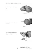
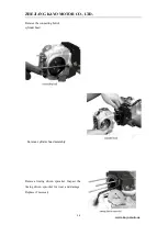
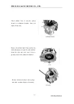
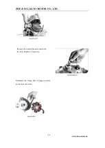
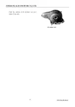
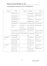
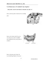
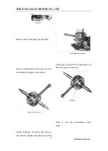
Remove  the  cover  of  right  crankcase  half. 

Check  whether  the  oil  seal  of  starting  shaft 

and  seal  edge  of  gearshift  lever  are  worn. 

Replace if necessary. 


Summary of Contents for A150

Page 1: ...ZHEJIANG KAYO MOTOR CO LTD WWW RIDEKAYO COM Model A150 STORM 150 Service Manual ...

Page 2: ...ments disassembly installation inspection points and specifications Please read the manual carefully and follow the instructions closely when performing inspections and repairs this will increase the reliability performance and overall lifespan of the vehicle All contents in this manual are subject to improve and update without notice ...

Page 3: ...Contents Chapter 1 Maintenance information Chapter 2 Plastics and Body parts Chapter 3 Regular Maintenance and adjustment Chapter 4 Outer parts of engine Chapter 5 Engine internals Appendix Electrical schematic diagram ZHEJIANG KAYO MOTOR CO LTD ...

Page 4: ...he following warnings seriously it s important for regular maintenance especially important during engine maintenance Danger Be on high alert for danger Warning Be on alert for moderate danger Attention Be on alert for minor danger This manual may contain some potential risks when performing engine work and maintenance Please pay close attention to the above explanations Service technician or mech...

Page 5: ...he battery solution is touches eyes please flush immediately with plenty clean cold water and get medical treatment as soon as possible Battery and battery solution should be kept out of reach of children Battery charging will produce flammable and explosive gases if exposed to a source of fire or spark there is a risk of explosion or fire Please charge in well ventilated places 5 As gasoline is f...

Page 6: ...to corrosive materials please keep them from contacting volatile oils grease or liquids 10 Pack or inject recommended grease in specific places as stated in service manual 11 Use special tools when needed for disassembly and installation 12 Ball bearings can be rotated with finger to confirm whether the rotation is flexible and smooth Bearing axial and radial clearance is oversized Clean and greas...

Page 7: ...nd inner cables to fray and eventually break 21 When assembling any protective caps covers or boots make sure they are seated correctly in the respective grooves Engine Break in Proper Engine break in is necessary on new engines and newly rebuilt engines to help ensure that longevity and reliability of the engine components Recommended break in time is 20 hours as follows 0 10 hours Operate at no ...

Page 8: ...YO MOTOR CO LTD WWW RIDEKAYO COM schedule After Break in period is complete schedule the unit for an inspection and service 1 2 VIN Number Model STORM 150 A150 VIN number Engine number 1 VIN number 2Engine number ...

Page 9: ... LTD Dimensions Vehicle Specifications 1 Dimension L W H mm 1535 920 950 2 Handlebar height mm 930 3 Handlebar width mm 730 4 Rear fender height mm 700 5 Seat height mm 705 6 Min ground clearance mm 90 7 Wheelbase mm 1040 8 Front width outside of tires mm 725 9 Rear width outside of tires mm 705 10 Turning radius mm 2500 11 Turning angle degree 46 1 12 Net weight Kg 105 ...

Page 10: ...linder diameter mileage mm mm 57 56 5 Compression ratio 9 2 1 6 engine weight kg 21 7 Max Power kg rpm 8 2 8000 8 Max torque N m rpm 8 0 5500 9 Ignition method CDI non adjustable ignition 10 Lubrication mode Combination oil slinger and oil pump 11 Fuel consumption g Kw h 367 12 Start type Electric 13 Tank volume 6 5L 14 Clutch type Multiple disc and oil bath clutch 15 Carburetor PZ27 16 Gear range...

Page 11: ...fer to left table Oil pump rotor Radial clearance of inner and outer rotors 0 07 mm 0 15mm 0 2mm Radial clearance between outer rotor and pump body 0 03 mm 0 10mm 0 12mm Axial clearance between rotor surface and pump body 0 023 mm 0 055mm 0 12mm Oil pressure 1500r min 90 200 kPa 400kPa General 240 kPa 6000r min 90 600 kPa 700kPa general 600 kPa Air intake system see engine section Frame 18 Drive s...

Page 12: ...pressure 4 0 PSI Brake system Item Standard Limitation Front brake disc thickness 3 5mm 3mm Brake lever stroke 5 10mm Braking force 400N m Rear brake disc thickness 3 5mm Brake lever stroke 10 20mm Braking force 500 N m Ignition device Item Standard Ignition method CDI electric ignition Spark plug Type Resistor type spark plug Standard A7RTC torch Gap 0 6 0 7mm Spark character 8mm one bar ...

Page 13: ...ine fuse 15A Light Headlight E4 35W Taillight brake light LED Gear indicator Digital Valve mechanism cylinder cover see engine section Cylinder piston piston ring crank connecting link see engine section 1 4 Fastener Torque Specifications Note When installing threads please manually attach 2 3 turns of thread first Torque Specifications chart No Item install position Bolt specification Class Momen...

Page 14: ...5 8 8 35 45 7 Rear swing arm bolt M10 1 25 10 9 58 71 8 Shock bolts M12 1 25 8 8 50 60 9 Brake Rear disc M8 8 8 18 25 with blue thread sealants 10 Front disc M6 10 9 15 20 with blue thread sealants 11 Caliper M8 10 9 29 35 with blue thread sealants 12 Front brake tee M8 8 8 18 25 13 Rear axle Rear axle M12 1 25 8 8 55 65 14 Nut M27 1 5 80 90 15 Chain tensioner bolt M6 8 8 8 12 16 Handlebar clamps ...

Page 15: ... coil M6 8 8 7 11 21 Fuel tank body parts plastic fuel tank M6 8 8 7 11 22 fuel tank switch M6 8 8 7 11 23 Pegs floorboards M8 8 8 18 25 with blue thread sealants 24 Brush guards M6 8 8 8 12 25 Plastic screw TM6 7 11 26 Screw for headlight and plastic ST4 2 3 5 Tightening moment at specified position engine see engine section Engine service tool see engine section Engine special tool see engine se...

Page 16: ...t bolts swing arm a arms 6 Bushings Bearings 7 Rear axle liner bushings tubes 8 Rear axle bearing and oil seal 9 Steering column clamp Note please coat inside of handlebar grip with grip glue before installing Engine operating materials and installation accessories see engine section Engine operating materials include lubricating oil engine oil Grease and may require thread sealant or thread lock ...

Page 17: ...ZHEJIANG KAYO MOTOR CO LTD WWW RIDEKAYO COM Main Harness front brake line Combination switch wires Choke cable Throttle cable Brake light switch wires ...

Page 18: ...p switch Neutral gear connector analog models Gear indicator connector Digital indicator models combination switch connector Electric lock Key switch Starter Relay Reverse gear indicator analog models Battery positive CDI headlight Battery negative ...

Page 19: ...ZHEJIANG KAYO MOTOR CO LTD WWW RIDEKAYO COM Ignition coil Voltage regulator Rear light Brake light switch connector ...

Page 20: ...ZHEJIANG KAYO MOTOR CO LTD WWW RIDEKAYO COM Stator ignition pickup gear indicator connector Ground cable ...

Page 21: ...enance cautions Operation cautions 1 When replacing plastics parts please install new warning labels stickers and riveted tags to the new plastics 2 This chapter is about the dismounting the body plastics 2 2 Installation torque M8 bolt 18 25N m TM6 bolt 7 11 N m M6 bolt 8 12 N m 2 3 Hood handlebar seat plastic parts rear body front body and middle guard front guard plastic pedals 2 3 1 Hood Disas...

Page 22: ...1 and 2 note replace hood plastic if any of the tabs broke during disassembly 2 3 2 Handlebar Disassembly 1 Cut off power first disconnect battery 2 Cut plastic cable ties then disconnect the combination switch stop switch and remove right grip 3 Remove the screws from the throttle cap to access and disconnect the throttle cable 4 Remove combination switch screws and choke cable 5 Remove the 4 han...

Page 23: ... 1 after install make sure to double check electrical connections wire cable and hose routing 2 3 3 Seat Disassembly Locate the seat latch under the seat Pull the latch to release Then pull and lift to remove the seat Combination switch Front brake Indicator panel Throttle seat Choke cable switch Handle bar riser ...

Page 24: ...aneously push down and forward until the latch locks into place 2 3 4 Front Bumper Disassembly 1 The mounting bolts in order Then remove the front bumper Installation 1 Position the front bumper lining up mounting holes install the mounting bolts loosely Then adjust bumper into position and tighten bolts Seat latch Mounting bolts ...

Page 25: ...Body Disassembly 1 Disconnect all necessary electrical connectors 2 Disassemble plastic parts fixing bolts1 2 3 4 5 6 7 8 9 10 in order on both sides 3 Remove the plastic body note remove the handlebar and hood before removing plastic body 3 4 1 2 7 8 9 5 6 10 ...

Page 26: ...ly check all electrical connectors cable and hose routing after installation 2 3 6 Middle guard Disassembly 1 Remove the mounting bolt 1 and 2 2 Remove the middle guard Installation Install in reverse order from disassembly Note replace mounting bolts nuts and rubber washers if damaged or worn 2 3 7 Rear body 1 2 ...

Page 27: ...ke the rear body off Installation Install in reverse order from disassembly Note replace locking nuts and rubber washers as needed 2 3 8 Front body Disassembly Note remove the handlebar hood and middle guard 1 Remove the front body mounting bolts1 2 3 4 5 6 7 2 Remove the key switch headlight connector then remove the front body 1 2 3 4 5 6 ...

Page 28: ...O COM Installation 1 Install in reverse order from disassembly Replace mounting bolts nuts and rubber washers as needed when worn check all electrical connectors cable and hose routing after installation 2 3 9 Foot peg guards 5 1 2 3 4 6 7 ...

Page 29: ...1 2 3 4 2 Remove the foot guard Installation Install in reverse order of disassembly Note replace mounting bolts nuts and rubber washers in time once they worn 2 3 10 Pedal Disassembly floorboard foot peg 1 Remove the mounting bolts 1 2 3 4 2 Remove peg bracket and foot peg 1 2 3 4 ...

Page 30: ...shers in time once they worn 3 Regular maintenance and adjustment 3 1 Maintenance information 3 2 Maintenance period 3 3 Inspection ways 3 4 Steering column and brake system 3 5 Wheel 3 6 Suspension system 3 7 Gear box and fuel system 3 8 Throttle check 3 9 Light device 3 10 Shock absorber selection 3 1 Maintenance information Warnings 1 2 3 4 ...

Page 31: ...period Engine maintenance is a regular periodic work due at certain time intervals for engine maintenance keeping up on standard maintenance will increase the lifespan and reliability of the components the following is the A150 engine maintenance period table Note the contents in the table is based on normal conditions if bike is ridden in dusty muddy or wet areas maintenance should be performed m...

Page 32: ...t Tear and damage of brake disc Replace the disc in time when front or rear brake working disc s thickness is less than 3mm Brake pad Tear and damage of brake pad The minimum brake pad friction plate thickness 1 5mm less than 1 5mm replace it Driving system Wheel Tire pressure front 45kPa 0 45kgf cm2 4 0PSI rear 45kPa 0 45kgf cm2 4 0PSI Crack and damage of wheel Tire groove depth and abnormal wear...

Page 33: ...nsmission and lubrication tightness of fixing bolt If chain wheel and chain wear severity replace it Electrical device Ignition device State of spark plug timing Battery Terminal connections Electric circuit Corrosion or damage connectors Fuel device Fuel leak Throttle condition Throttle knob clearance 3 5mm Lightingdeviceandindicators function Exhaustpipeandmuffler Torqueonallfasteners Functionof...

Page 34: ... linkages ball joints or fastening hardware then repair If it s caused by steering column tighten the bottom lock nut on steering column or you can also disassemble the steering column to check bearing and clamps Keep vehicle in steady place and turn the handlebars slowly making sure movement is smooth ...

Page 35: ...10mm Brake pump assembly Check the fluid level at the sight glass on the master cylinder If brake is below the lower limit stop using the vehicle immediately and ispect for leaks at master cylinder hoses fittings and connections If fluid is low remove top of master cylinder and add DOT4 brake liquid to limit position Note When adding brake fluid do not mix with dust or water always add fluid from ...

Page 36: ...pads Check thickness of pads If it s less than 1 5mm replace Check for damage cracks and uneven wear Replace pad set if out of specification Note Replace pads in sets 3 5 Wheel With the atv on a jack of atv lift Lift the front wheels off the ground Push and pull the wheel in and out as shown in the diagram If there is movement check torques on hub steering shafts spindles If there is still movemen...

Page 37: ... place Note after the adjustment of front toe in drive the vehicle slowly and make sure vehicle tracks straight and true After test ride check measurement again to make sure toe in is locked into place Tire pressure Check the tire pressure with a tire pressure gauge Pressure range 4 6PSI Note Check the tire pressures while the tire is cool If tire pressure is out of specification please adjust to ...

Page 38: ... 3 6 Suspension system Keep vehicle in a horizontal position and compress up and down several times according to the pictures If there is shaking or abnormal sounds check whether there is oil leakage in the shock absorber or check for damage or loosening in the fastening parts 3 7 Gear shifter and fuel system ...

Page 39: ...es for aging dry rot cracks and damage Replace if any damages are found or if more than 2 years old 3 8 Throttle check Check the free stroke of the thumb throttle lever Press the accelerator several times as shown in the Diagram check the free play of the thumb throttle Check for any sticking or slow return of the lever Thumb throttle should be easy and smooth to push and should snap back quickly ...

Page 40: ...AYO COM Freeplay 3 5mm Adjust throttle free play if out of specification Pull back rubber sleeves 1 2 Loosen lock nut 3 and barrell adjuster 4 then adjust throttle free play to within specification Speed limiting device adjustment 1 3 4 2 ...

Page 41: ...tle as much as possible for safety As the riders skills progress the limiter screw can be adjusted outward Throttle limiter is set from the factory with a tamper proof screw If necessary the screw can be removed with pliers and replaced with a phillips head screw Suspension pre load adjustment Front shock is non adjustable Rear shock can be adjusted from 1 to 5 This is set in the middle at 3 from ...

Page 42: ...d injury To protect finishes please wrap the frame plastics or any vulnerable finishes before removing engine parts or performing maintenance on engine Please dispose of liquid such as oils and coolants properly Use drain pans to prevent spills The engine does not need to be removed for the following operations oil pump carburetor air filter cylinder head cover start motor cylinder head cylinder b...

Page 43: ... areas away form these hazards when refueling or working on the fuel system and its related components Fuel tank removal Remove the plastic body parts remove fuel lines from tank and fuel valve then remove tank mounting bolts and tank Fuel tank pictures may differ from tanks on U S models Installation Install tank in reverse order from disassembly Check for aged worn dried or cracked hoses replace...

Page 44: ...Installation Installation shall be in the reverse order of removal Make hose clamp is in the groove and any vacuum lines are hooked up correctly 4 4 Exhaust system Disassembly Disassemble the clamp between muffler and exhaust head pipe then remove the muffler mounting bolt to remove muffler Air filter clamp ...

Page 45: ...haust flange nuts then remove exhaust pipe Assembly Installation shall be in the reverse order of removal do not reuse exhaust head pipe gasket always replace replace muffler gasket and any hardware for exhaust if damaged or deformed Mounting bolt clamp 1 2 ...

Page 46: ...te Remove floorboards pegs carburetor intake manifold and oil cooler first 1 Remove the engine front sprocket side cover then remove chain Remove the ground lead and all electrical connectors exhaust pipe and gearshifter Gear indicator wires Stator ignition pickup wires Start motor cable Ground lead ...

Page 47: ... MOTOR CO LTD www kayomoto us 47 Remove the 3 engine mounting bolts 2 Remove the engine from the right side of vehicle Installation Ignition coil cap Gear shift lever Engine mounting bolt Bottom engine mounting bolt ...

Page 48: ... 1000cm3 Moment 1kgf 9 80665N Danger Warning attention Danger Be on high alert for danger Warning to be alert to moderate danger Attention to be alert to minor danger This manual may doesn t contain some potential risks in engine work and maintenance the service operator should also have basic mechanical knowledge General precautions Warning Proper maintenance is very important to engine reliabili...

Page 49: ... other toxic chemicals properly Warning If parts need to be replaced during maintenance please use parts recommended or provided by Kayo Disassembled parts that need to be reused should be arranged in order to aid in re assembly Choose special tools as specified in the maintenance manual Ensure that parts used in assembly are clean and lubricated where required Use special lubricants binders and s...

Page 50: ...tc therefore a standard break in is very important at the beginning of the its use it can make the moving parts to adapt to each other correctly work form a smooth mating surface Through this process the engine will have excellent performance and reliability Recommended break in time 20 hours details as follows 0 10 hours Avoid continuous operation constantly changing speed and not operating in a ...

Page 51: ... us 51 5 4 Engine number Engine head displacement label 5 4 Maintenance Subsidiary maintain times Items Odometer reading 1000km 4000km 8000km 12000km Fuel system Clean Clean Clean Clean Oil filter Clean Clean Clean Clean Engine Number label ...

Page 52: ...just Adjust Adjust Adjust Drive chain Adjust and lubricate per 5000km Battery Charge Charge Charge Charge Brake disc Check Adjust Adjust Replace Brake system Adjust Adjust Clean Clean Brake light switch Adjust Adjust Adjust Adjust Illuminating system Check Check Adjust Adjust Clutch Adjust Adjust Adjust Adjust Shock absorber Adjust Adjust Clean Clean Nuts bolts Tighten Tighten Tighten Tighten Fron...

Page 53: ...oto us 53 Left view of the 150 engine is shown in the figure Remove the acorn nuts of cylinder head from cylinder studs Remove cylinder head Check the state of paper pad gasket Replace if necessary Dismantle the fixing bolt of left cover ...

Page 54: ...ZHEJIANG KAYO MOTOR CO LTD www kayomoto us 54 Remove left cover and inspect the paper pad gasket for damage Replace if necessary Dismantle the fixing bolt of right cover ...

Page 55: ... us 55 Remove the right cover of cylinder head Inspect the gasket for damage and replace if necessary Remove intake and exhaust valve caps Check o rings and replace if worn or if reuse is questionable Remove the fixing bolts of cam sprocket ...

Page 56: ...O MOTOR CO LTD www kayomoto us 56 Remove the connecting bolt of cylinder head Remove cylinder head assembly Remove timing driven sprocket Inspect the timing driven sprocket for wear and damage Replace if necessary ...

Page 57: ...stion chamber Clean and replace if necessary Remove the cylinder head Pour gasoline into inlet exhaust pipe to inspect the seal condition Grind the valve and valve seat if there is gasoline leak into the combustion chamber Remove intake and exhaust valve springs and check condition Replace if necessary ...

Page 58: ...LTD www kayomoto us 58 Inspect the oil seal intake and exhaust valves for damage Replace if necessary Remove the spark plug to clean the carbon deposits and dirt Check the spark plug gap and set it to 0 6 to 0 7 if necessary ...

Page 59: ...t muffler pipe Replace the valve guide The cylinder gasket is broken Air leakage between the cylinder head and cylinder The engine starts hard or fails to start Insufficient engine output Engine speed changes during idle run Replace the cylinder head gasket The fixing nut is not properly tightened Air leakage between the cylinder head and cylinder The engine starts hard or fails to start Insuffici...

Page 60: ...ket and dowel pins check for wear and damage Replace if necessary Dismantle the fixing bolt of timing chain of guide wheel Remove the guide wheel of timing chain to inspect for wear and damage Replace if necessary Dismantle connecting bolt of cylinder block Remove the cylinder block Remove the circlip of piston pin ...

Page 61: ...R CO LTD www kayomoto us 61 Remove the piston of piston pin to check whether it is damaged Replace if necessary Remove and replace gaskets Check whether there is residual gasket on cylinder Clean and scrape if necessary ...

Page 62: ...er walls Replace if worn or if reuse is questionable Check whether the internal diameter has exceed the limit value Measure the diameter at top middle and bottom of cylinder The limit value is 52 05 mm Replace the cylinder block if it worn beyond repair out of round or gouged ...

Page 63: ...oor idle speed and high fuel consumption Grind the cylinder end surface or replace the cylinder body The cylinder is badly worn The fitting clearance between the cylinder and position position ring is too wide The engine starts hard or fails to start Insufficient engine output Poor engine idle speed Thick blue and white fume form the exhaust muffler pipe Repair with boring machine or replace the c...

Page 64: ...D www kayomoto us 64 Check the conditon of right crankcase cover and replace if necessary Left view of right crankcase half is shown in fig and check whether bearing of main shaft and countershaft are worn Replace if necessary ...

Page 65: ...f necessary Left view of left crankcase is shown below and check whether the oil seal of countershaft and oil seal edge of gearshift lever are worn Replace if necessary Right view of right crankcase half is shown in fig and check whether bearing of main shaft and countershaft are worn Replace if necessary Dismantle fixing bolt of left crankcase cover ...

Page 66: ...ZHEJIANG KAYO MOTOR CO LTD www kayomoto us 66 Remove the neutral indicator and check the state Replace if necessary Dismantle the fixing bolt of magneto stator and remove the stator ...

Page 67: ...ZHEJIANG KAYO MOTOR CO LTD www kayomoto us 67 Check the condition of left crankcase cover and replace if necessary ...

Page 68: ...linder The engine starts hard or fails to start Insufficient engine output Engine speed changes during idle run Repair the threaded or replace the crankcase The bolt of the cylinder is broken The same as front The same as front Replace the cylinder bolt The oil seal is damaged or the oil seal edge is damage worn aged Oil leakage is ineffective Oil leakage from the oil seal Replace the oil seal 更换油...

Page 69: ... assemble and maintain crankshaft connecting rod Remove the fixing bolt of crankcase from its holding place Remove left crankcase half Take care not to forget the washer of mainshaft and countershaft when removing the left crankcase Remove the paper pad to inspect for wear and damage Replace if necessary ...

Page 70: ...rod assembly Inspect connecting rod bearing for wear and damage Replace if necessary Check gap of big end of connecting rod Reset the gap if necessary Check diameter of piston pin using a micrometer Replace the piston pin if the value is over the maintenance limit value ...

Page 71: ... of connecting rod bearing Replace the conrod if the jumping is large Check the side gap between piston ring and piston groove using a feeler gauge Replace the piston if the gap is too wide Check whether there is excessive carbon deposit on piston top and groove Remove if necessary ...

Page 72: ...ue Assemble the piston ring according to the size and check whether piston ring is damaged or the elasticity is weaken Replace if necessary For the troubleshooting of crankshaft connecting rod mechanism please refer to the followingtable Maintenance of Crankshaft Connecting Rod Mechanism Description Damage from Trouble Cause Correction Carbon deposit on piston top 活塞顶部积碳 The engine over heats Remo...

Page 73: ... Replace the crankshaft connecting rod Bearing The big end needle bearing is over worn Radial and axes gap of the connecting rod big end is too large Striking sound of the big end bearing and of the cylinder Replace the crankshaft connecting rod 更换曲轴连杆 The crankshaft bearing is over worn or damaged Abnormal sound during the crankshaft bearing transmission Replace the crankshaft bearing Piston ring...

Page 74: ... or twisted Striking sound of the cylinder Replace the connecting rod The big end hole is over worn Radial and axes gap of the connecting rod big end is too large Striking sound of the big end bearing and of the cylinder Replace the connecting rod Timing sprocket The gear is over worn of damage Abnormal sound during sprocket driving Replace the timing sprocket 5 5 Maintenance of Mechanism Disassem...

Page 75: ... of inlet and exhaust valve Remove inlet vale stem and exhaust valve stem take care and don t miss the valve clip Measure length of valve spring to check whether the spring is damaged or worn Replace if necessary Remove the spring of inlet and exhaust valve to inspect for wear and damage Note when assemble the valve spring make sure its dense end downward ...

Page 76: ...r clipper Replace the valve stem if the valve is beyond the maintenance limit valve Measure the width of valve contact surface to check whether the contact surface is rough or abnormal Replace the valve stem if the valve is large than 1 5mm Check whether the valve stem is distored Replace if necessary ...

Page 77: ...ck the state of camshaft Replace if necessary Check the gap of rocker arm shaft and rocker arm Replace the rocker arm shaft and rocker arm if the gap is large Check the external diameter of rocker arm using a micrometer Replace the rocker arm shaft if the valve is beyond the maintenance limit valve ...

Page 78: ...wheel of timing chain to inspect for wear and damage Replace if necessary Remove the fixing bolt of timing tensioner and check the state Replace if worn or if reuse is questionable Remove the timing tensioner arm to inspect for wear and damage Replace if necessary ...

Page 79: ...yomoto us 79 Remove the oil tube and spring and check the state Replace if necessary Remove the small timing chain and check the state Replace if necessary Adjust valve clearance as follows Remove the valve cap and check the condition ...

Page 80: ...rn magnetic rotor counterclockwise to make piston locate at top dead center and make T mark aimed to the mark of left crankcase cover Check whether the O mark on cam sprocket is aimed to the gap of cylinder head Readjust if necessary Set the valve clearance of rear cylinder to 0 05mm 0 06mm ...

Page 81: ...O MOTOR CO LTD www kayomoto us 81 For the troubleshooting of engine distribution mechanism please refer to the followingtable Maintenance of Distribution Mechanism Descriptions Damage form Trouble Cause Correction ...

Page 82: ...d Replace the rocker arm The rocker arm shaft is over worn Big gap between the rocker arm and rocker arm shaft Valve striking sound Replace the rocker arm shaft Valve The valve clearance is too small The valve is impossible to close completely The engine starts hard or fails to start Insufficient engine output Engine speed changes during idle run Readjust the valve clearance to 0 05 0 06mm The val...

Page 83: ...d It is impossible to close the valve completely The engine starts hard or fails to star Replace the valve Valve spring The spring is ineffective or fractured It is impossible to fit the valve and the valve seat tightly The engine starts hard or fails to star Sound of the cylinder head Replace the valve spring Disassemble assemble and maintain carburetor Dismantle the fixing bolt of carburetor and...

Page 84: ... fixing bolt of float chamber cap Remove the float chamber cap Remove the water and debris in the cap if necessary Check the state of seal ring and replace if it is aging Remove the float needle valve to inspect for wear and damage Replace if necessary Remove the throttle and oil needle and check the condition replace if necessary ...

Page 85: ...t of float case by moving the float up or down Take out the main jet to check whether the jet hole is clogged Clean if necessary Remove the main nozzle to check whether small hole is clogged Clean with compressed air if necessary Remove the idle jet and check for plugged Clean the jet with compressed air if necessary ...

Page 86: ... Standard Tighten mixture screw and turn it one And a half turns clockwise Measure height of float case to check whether it is distorted or there is fuel inside If height is incorrect which indicates carburetor leaks or the fuel supply is insufficient Adjust the oil needle to the third tier If the clip rises concentration of mixture becomes dilute and if falls it becomes thick ...

Page 87: ...er to the followingtable Description Damage form Trouble Cause Correction Air filter Too much dust on the filter core The engine starts hard or fails to start Insufficient engine output poor performance of engine during idle run Excessive fuel consumption The exhaust muffler pipe fumes strongly black Clean the filter core The filter core is fractured or chapped Engine air suction noise is too loud...

Page 88: ...e assemble maintain and manage motor starter Remove the fixing bolt from left crankcase cover Dismount gear indicator switch fixing bolt remove gear indicator to check the wear or damage condition replace it if necessary Remove left crankcase cover stator cover ...

Page 89: ...ZHEJIANG KAYO MOTOR CO LTD www kayomoto us 89 Remove gasket to check it s condition If the gasket is worn or reusable please replace Remove fixing bolts of stator and trigger ...

Page 90: ...ZHEJIANG KAYO MOTOR CO LTD www kayomoto us 90 Check stator status with multimeter If wear and tear or re use problems please replace the new accessories Remove rotor fixing nut Remove rotor with puller ...

Page 91: ... check magnets if necessary replace Remove starter clutch fixing bolt Remove clutch to check for wear and damage condition of clutch seat pulley and spring If it necessary replace it Check the condition of drive sprocket and transmission gear If necessary replace ...

Page 92: ...NG KAYO MOTOR CO LTD www kayomoto us 92 Disassemble start sprocket press board Dismount starter chain tensioner check the condition If worn or damaged replace it Remove the snap ring from start motor sprocket ...

Page 93: ...ZHEJIANG KAYO MOTOR CO LTD www kayomoto us 93 Disassemble the drive sprocket and chain Dismount the fixing bolt of start motor Remove starter motor ...

Page 94: ... motor wiring and spline condition if necessary replace it Disassemble the oil separation disc and check the condition if it necessary replace it Check oil seal edges for wear Replace as necessary Remove the seal and check the oil ring condition if it worn replace ...

Page 95: ...e Replace carbon brush spring Armature commentator surface is fouled Starter motor has insufficient rotation force Clean the commentator surface With gasoline or alcohol Armature commentator surface is spotted burnt or damaged Starter motor has insufficient rotation force Polish the surface against the Commentator with fine abrasive Paper Make the cut on the mica Plate between each commentator Pie...

Page 96: ...ZHEJIANG KAYO MOTOR CO LTD www kayomoto us 96 Circuit diagram ...

Reviews: