background image

ZHEJIANG KAYO MOTOR CO., LTD.


WWW.RIDEKAYO.COM


Tire pressure


Check the tire pressure with a tire pressure gauge. (pressure range: 4~6PSI)   

Note:  Check  the  tire  pressures  while  the  tire  is  cool  .  If  tire  pressure  is  out  of 

specification  please  adjust  to  within  range  specified.  Riding  with  tires  out  of 

specified  range will  affect vehicle handling and may cause premature wear and 

or damage to tire tread.


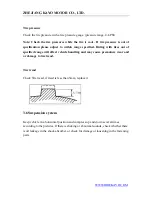
Tire tread     

Check Tire tread, if tread is less than 3mm, replace it. 


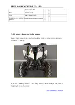
3.6 Suspension system 

Keep vehicle in a horizontal position and compress up and down several times 

according to the pictures. If there is shaking or abnormal sounds, check whether there 

is oil leakage in the shock absorber, or check for damage or loosening in the fastening 

parts. 


Summary of Contents for JACKAL 200

Page 1: ...ZHEJIANG KAYO MOTOR CO LTD WWW RIDEKAYO COM Model A200 JACKAL 200 Service Manual...

Page 2: ...ents disassembly installation inspection points and specifications Please read the manual carefully and follow the instructions closely when performing inspections and repairs this will increase the r...

Page 3: ...Content Chapter 1 Maintenance information Chapter 2 Plastics and Body parts Chapter 3 Regular Maintenance and adjustment Chapter 4 Outer parts of engine Chapter 5 Engine internals Appendix Electrical...

Page 4: ...t during engine maintenance Danger Be on high alert for danger Warning Be on alert for moderate danger Attention Be on alert for minor danger This manual may contain some potential risks when performi...

Page 5: ...flammable and explosive gases if exposed to a source of fire or spark there is a risk of explosion or fire Please charge in well ventilated places 5 As gasoline is flammable and explosive Pay attenti...

Page 6: ...installation 12 Ball bearings can be rotated with finger to confirm whether the rotation is flexible and smooth Bearing axial and radial clearance is oversized Clean and grease bearings with a tight s...

Page 7: ...y break 21 When assembling any protective caps covers or boots make sure they are seated correctly in the respective grooves Break in of engine Proper Engine break in is necessary on new engines and n...

Page 8: ...te During break in period do everyday maintaining and eliminate hidden trouble in time Break in period ended make a maintenance for the vehicle then putted into formal use 1 2 VIN Number Model A200 VI...

Page 9: ...cc Utility ATV 4 Company ZHEJIANG KAYO MOTOR CO LTD Dimensions Vehicle Specifications 1 Dimension L W H mm 1700 1050 1080 2 Handlebar height mm 1080 3 Handlebar width mm 860 4 Rear height mm 1010 5 Gr...

Page 10: ...Single cylinder four stroke air cooling 3 Distribution SOHC by chain 4 Cylinder diameter mileage 65X59mm 5 Compression ratio 9 2 1 6 Lubrication mode Combination splash and pressure feed 7 Fuel pump R...

Page 11: ...ngle stage Gear ratio of forward gear Gear ratio of forward gear Overall Frame 20 Drive sprocket ratio 45 14 21 Output type Chain drive rear wheel drive 22 Brake type Front and rear disc 23 Suspension...

Page 12: ...0 15mm 0 2mm Radial clearance between outer rotor and pump body 0 03 mm 0 10mm 0 12mm Axial clearance between rotor surface and pump body 0 023 mm 0 055mm 0 12mm Oil pressure 1500r min 90 200 kPa 400k...

Page 13: ...ke handle stroke 10 20mm Braking force 500 N m Ignition device Item Standard Ignition method CDI electric ignition Sparking plug Type Resistor type spark plug Standard ATR7C torch Gap 0 6 0 7mm Spark...

Page 14: ...ne section 1 4 Tightening moment of fastener Note When installing threads please manually attach 2 3 turns of thread first Torque Specifications chart No Item install position Bolt specification Class...

Page 15: ...mp M8 10 9 class 29 35 11 Front brake tee M8 8 8 18 25 12 Rear axle Rear axle M12 1 25 8 8 55 65 13 Nut M27 1 5 80 90 14 Chain bolt M6 8 8 8 12 15 Turning Clamp locking bolt hexagon M8 10 9 18 25 16 S...

Page 16: ...ine section Engine service tool see engine section Engine special tool see engine section 1 5 lubricating grease and sealant No Position Effect Grease 1 Dust cap for rocker arms lubrication XHP222 2 B...

Page 17: ...before installing Engine operating materials and installation accessories see engine section Engine operating materials include lubricating oil engine oil Grease and may require thread sealant or thr...

Page 18: ...MOTOR CO LTD WWW RIDEKAYO COM headlight Electric lock Key switch For clutch switch Reverse gear indicator analog models Neutral gear connector analog models Headlights combination switch connector Vol...

Page 19: ...KAYO MOTOR CO LTD WWW RIDEKAYO COM Regulator rectifier Tail light Igntition coil Relay connector Battery positive Ignition Battery negative Start motor cable Brake light switch connector Rear light c...

Page 20: ...ng plastics parts please install new warning labels stickers and riveted tags to the new plastics 2 This chapter is about the dismounting the body plastics 2 2 Installation torque M8 bolt 18 25N m TM6...

Page 21: ...dlebar 2 3 3 Disassembly 1 Cut off power first disconnect battery 2 Cut plastic cable ties then disconnect the combination switch stop switch and remove right grip 3 Remove the screws from the throttl...

Page 22: ...trical connections wire cable and hose routing 2 3 3 Seat Disassembly Locate the seat latch under the seat Pull the latch to release Then pull and lift to remove the sea Installation To install line t...

Page 23: ...ting holes install the mounting bolts loosely Then adjust bumper into position and tighten bolts 2 3 5 Plastic Body Disassembly 1 Disconnect all necessary electrical connectors 2 Disassemble plastic p...

Page 24: ...IANG KAYO MOTOR CO LTD WWW RIDEKAYO COM Installation Install the plastic body in reverse order from disassembly check all electrical connectors cable and hose routing after installation 1 2 3 4 5 6 7...

Page 25: ...ar body Disassembly 1 Remove the mounting bolts1 2 3 4 5 6 7 8 and corresponding bolts on opposite side Take the rear body off Installation Install in reverse order from disassembly Note replace locki...

Page 26: ...ZHEJIANG KAYO MOTOR CO LTD WWW RIDEKAYO COM 2 3 7 Middle guard Disassembly 1 Remove the mounting bolt 1 2 3 4 2 Remove the middle guard Installation Install in reverse order from disassembly 1 2 3 4...

Page 27: ...ting bolts nuts and rubber washers if damaged or worn 2 3 8 Front body Disassembly Note remove the handlebar hood and middle guard 1 Remove the front body mounting bolts1 2 3 4 5 2 Remove the key swit...

Page 28: ...r washers as needed when worn check all electrical connectors cable and hose routing after installation 2 3 9 Foot peg guards Disassembly 1 Remove mounting bolts 1 2 3 2 Remove the foot guard Installa...

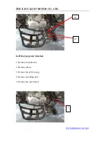
Page 29: ...DEKAYO COM Disassembly floorboard foot peg 1 Remove the mounting bolts 1 2 3 4 5 2 Remove peg bracket and foot peg Left foot peg front bracket 1 Remove front bracket 2 Remove plastic 3 Remove screws 1...

Page 30: ...ZHEJIANG KAYO MOTOR CO LTD WWW RIDEKAYO COM Left foot peg rear bracket 1 Remove front bracket 2 Remove plastic 3 Remove the left foot peg 4 Remove mounting nut 1 5 Remove the rear bracket 3 4 1 2 1...

Page 31: ...absorber selection 3 1 Maintenance information Warnings Note Do not run the engine in unventilated places because the exhaust contains carbon monoxide CO and other toxic components To prevent burns d...

Page 32: ...spection L lubrication R replace 10 hours or 300km 20 hours or750km per 50 hours or1500km per 100 hours or3000km or one year per 200hours or6000km 2 years Remark Engine Lubricating oil and air filter...

Page 33: ...on the wheel the residual groove depth should greater than3mm Axle torque Front wheel bearing vibration Rear wheel bearing vibration Suspensio n Suspension arm Shaking of connection part and damage of...

Page 34: ...andlebar firmly as it shown in the picture to check if it s shaking If there is a shaking check it s caused by steering column linkages ball joints or fastening hardware then repair Functionofmuffler...

Page 35: ...m check steering rods and connecting points for damage Note the steering must be smooth and move freely between left locked position to right locked position Steering system free play Check movement b...

Page 36: ...e disc and brake pads The brake pads caliper and disc are normal wear and tear items Check or replace the brake disc Check the surface of brake disc if it is worn damaged bent or grooved replace If th...

Page 37: ...orn or damaged Front wheel size On a level surface with handle bars straight check the front wheel toe in The front wheel relative to the forward direction of the vehicle is A in front and B behind th...

Page 38: ...ding with tires out of specified range will affect vehicle handling and may cause premature wear and or damage to tire tread Tire tread Check Tire tread if tread is less than 3mm replace it 3 6 Suspen...

Page 39: ...stem Changing gears with the shift lever should be smooth and gear changes should have a positive firm feeling Fuel device Remove the plastic parts first Check fuel vacuum and vent lines for aging dry...

Page 40: ...ress the accelerator several times as shown in the diagram check the free play of the thumb throttle Check for any sticking or slow return of the lever Thumb throttle should be easy and smooth to push...

Page 41: ...tment Speed limit device is used to restrict throttle opening Inspect the thread length limit of speed limit screw Suspension pre load adjustment Front shock is non adjustable Rear shock can be adjust...

Page 42: ...e on engine Please dispose of liquid such as oils and coolants properly Use drain pans to prevent spills The engine does not need to be removed for the following operations oil pump carburetor air fil...

Page 43: ...he plastic body parts remove fuel lines from tank and fuel valve then remove tank mounting bolts and tank Fuel tank pictures may differ from tanks on U S models 4 3 Air filter system Disassembly Loose...

Page 44: ...al Make hose clamp is in the groove and any vacuum lines are hooked up correctly 4 4 Exhaust system Disassembly Disassemble the clamp between muffler and exhaust head pipe then remove the muffler moun...

Page 45: ...and any hardeware for exhaust if damaged or deformed 4 5 Disassembly and installation of engine Disassembly 1 Remove the engine front sprocket side cover then remove chain 2 Remove the ground lead and...

Page 46: ...COM Remove the 3 engine mounting bolts 3 Remove the engine from the right side of vehicle Installation Installation shall be in the reverse order of removal 5 Engine 5 1 Maintenance information Cylin...

Page 47: ...e cylinder head cap Assemble cam shaft Install cylinder head Install cylinder head cap Maintenance Precautions General precautions Keep the oil routine on cylinder head clean and smooth Pre install lo...

Page 48: ...valve spring 48 35 47 5 Valve clearance 0 04 0 06 Cam base circle bounce 0 02 0 04 Item Standard mm Limited mm Valve Valve bar diameter Air intake 4 972 4 987 4 96 Air intake 4 96 4 975 4 94 Valve gu...

Page 49: ...is too larger or broken piston with cranks or too damaged cylinder inner diameter is larger or with cranks Black smoke 1 Valve guider pipe worn 2 Oil shield leaked or damaged 3 Cylinder head gasket le...

Page 50: ...ZHEJIANG KAYO MOTOR CO LTD WWW RIDEKAYO COM...

Page 51: ...er head cap 1 Remove four M6 20 fastening bolts from the cylinder head 2 Remove air chamber covers of air intake 3 Remove two M6 60 bolts two M6 35 bolts four M6 30 bolts and two A88 air intake pipe g...

Page 52: ...ZHEJIANG KAYO MOTOR CO LTD WWW RIDEKAYO COM Disassemble cylinder head 1 remove seal sleeves and cam shaft board 2 Remove GB T16674 M6 16 bolt and ZS500 6 5 1 5 18 locating plate gasket...

Page 53: ...AYO MOTOR CO LTD WWW RIDEKAYO COM 3 remove 2 bolts from tensioner then tensioner bolts assembly and gaskets 4 remove timing chain 5 remove cam shaft assembly 6 remove bolts which connect cylinder head...

Page 54: ...ZHEJIANG KAYO MOTOR CO LTD WWW RIDEKAYO COM 7 remove four nuts ZS500A and nuts M10 1 25 then gaskets 10 5 2 20 8 remove cylinder head Separate cylinder head cap...

Page 55: ...Remove air intake and exhaust swing arm shaft and swing arms Separate cylinder head Pressure the spring with valve tool to remove valve lock clap Then release tool to remove spring spring seat and va...

Page 56: ...and spring check Check if there is bend burn or abnormal damage of valve Measure diameter of valve bar Maintenance limited Intake 4 96mm exhaust 4 94mm Maintenance limited for contact width 1 5mm note...

Page 57: ...free length of valve spring 48 35mm Service limited value intake and exhaust spring 47 5 mm Swing arm and shaft check Replace in following condition swing arm worn damaged or the axial clearance is la...

Page 58: ...he cylinder with bad sealing replace head or valve 2 check if there is crank on spark hole and valve seat 3 check if the head is deformed and test the flatness with feeler gauge Valve seat check and a...

Page 59: ...it s movement measure the clearance between valve lever and guide pipe at last Service limited value intake 0 07 mm exhaust 0 08mm Guide pipe replacing Heat cylinder head to100 150 in thermotank take...

Page 60: ...at the same time then put on valve seal line start electric gun and turn valve After adjust check if you can seethe seal line of valve and seat ring if not adjust again or replace valve or cylinder h...

Page 61: ...heck if the lock clip in right position 5 Test sealing of cylinder head assembly Cylinder head cap assembly Put two swing arms into cylinder head cap and install shafts Install fixing plate bolts of s...

Page 62: ...ead gasket then locating pin 2 First Install cylinder head on A and B bolts second ZS500A and B bolt nuts washers third ZS500Aand B bolt nuts Note 1 Keep the cylinder body clean 2 nut tightening torqu...

Page 63: ...check if the timing mark on timing driven sprocket is in horizon with cover 4 Install hole cover and fixing plate of swing arm shaft on left front cove 5 Install tensioner to specific holes and fixed...

Page 64: ...1667 M6 60 bolts then set into oil pipe hole of cylinder head cap Make 2 GB T16674 M6 35 and 4 GB T16674 M6 30 through cylinder head cap and tight Tightening torque 11 13N m 5 adjust the clearance of...

Page 65: ...rankcase from dust specification Item Standard value mm Service limited value mm cylind er Inner diameter 77 77 01 77 018 Out of roundness 0 05 0 01 Flatness of cylinder surface 0 03 0 05 Outer diamet...

Page 66: ...0 08 clearance between cylinder and piston 0 035 0 045 0 07 piston pin outer diameter 15 994 16 15 99 connecting rod Inner diameter 16 015 16 025 16 04 clearance between connecting rod and piston pin...

Page 67: ...R CO LTD WWW RIDEKAYO COM Cylinder disassembly Remove chain guide plate to take the cylinder Clean up remained washer on cylinder Note It s easy to separate washers if put them into petrol Take care o...

Page 68: ...NG KAYO MOTOR CO LTD WWW RIDEKAYO COM Cylinder body check Check if the cylinder worn or damaged Measure cylinder inner diameter top middle and bottom position of piston stroke Service limited value 77...

Page 69: ...pliers then piston pin and piston Note Take care don t drop piston pin ring into crankcase Piston and piston ring check Remove piston ring Note keep piston ring well Measure clearance between piston r...

Page 70: ...if piston ring worn or cranked and groove worn Put piston ring into cylinder to measure end play Service limited value First ring 0 5mm Second ring 0 5mm Oil ring 1 4 mm Measure the inner diameter of...

Page 71: ...ton pin diameter Service limited value 15 99 mm Compute the distance between piston pin and piston Service limited value 0 025 mm Piston ring assembly 1 Clean piston ring groove completely 2 Install p...

Page 72: ...The piston ring end gap opening faces down 3 If the piston ring severe deformed replace 4 Keep piston ring from crank case Cylinder body assembly 1 Install cylinder locating pin and new gaskets 2 Smea...

Page 73: ...Clutch disassemlby Overshoot and start gear check Driving gear disassemlby Right body oil pump check Overshoot and start gear disassembly Gearshift check Right body oil pump disassembly Duplicate gear...

Page 74: ...ver and friction disc 0 1 0 3 0 6 Oil pump Radial clearance of outer and inner rotors 0 06 0 15 End clearance of rotor and plate 0 04 0 1 Troubleshooting Clutch If breakdown occurs it can adjust by ad...

Page 75: ...d 1 stopper plate curved or worn 2 wrong clutch adjustment Oil pressure is too low Trip stop of gearshift gear 1 oil pump damaged 1 stopper arm spring broken or the 2 pump driven gear broken elasticit...

Page 76: ...ump cover then drain the water remover cover and impeller last Right crankcase disassemblly 1 Drain oil first remove oil screens from both sides and oil screen assembly from body until the oil drain o...

Page 77: ...3 remove locking nuts and washers 4 remove central bush outer cover axle cover and washers 5 remove clutch push lever Driving overshoot and start gears disassembly 1 Remove driving gear locking nuts...

Page 78: ...e gear and oil pump assembly 3 Remove 3 GB T16674 M5 18 bolts from right oil pump cover then remove oil pump plate assembly and outer and inner rotors of oil pump Note There are 2 washers on oil pump...

Page 79: ...g motor tighten bolts then starting motor Gearshift disassembly 1 Remove five star plate bolts GB T70 1 M6 35 and five star plate 2 Remove gearshift arm parts 3 Remove tighten bolts washers and locati...

Page 80: ...ks the inserts loosen if so replace a new impeller 2 Check water sealed components oil seal and pump shaft if they re abnormal replace Note 1 Smear oil in pump shaft hole use specific tool to install...

Page 81: ...if only electric start ignore Clutch spring check Measure free length of clutch spring Service limited value 32 3mm Clutch friction disc check If the friction disc got worn or faded replace measure th...

Page 82: ...ance gauge Service limited value 0 14 mm Check the clearance of clutch outer cover and friction disc Service limited value 0 6 mm Clutch outer cover cheking Check if there is severe cranks on the oute...

Page 83: ...eck if the driving gear worn or damaged severely if so replace Overshoot clutch check Remove the rand from clutch end face to check if the wedge block worn or damaged Starting gear check Check the wea...

Page 84: ...if the gap bridge gear and gear assembly broken if so replace them 3 Check the right body oil pump plate condition if it worn or damaged replace it Staring motor and duplicate gear check Check the st...

Page 85: ...duplicate gear on duplicate gear shaft 2 Put duplicate gear washer on end face of duplicate gear 3 Install ring GB T894 1 15 on rand groove of duplicate gear shaft Gearshift mechanism assembly 1 Inst...

Page 86: ...ould in the same direction 2 The tighten torque of oil pump cover plate is 7 9 N m 3 Make sure the oil pump shaft works well 3 Install oil pump gear assembly on oil pump then install ring GB T894 1 10...

Page 87: ...e on inner hole of starting gear before installing Driving gear installation 1 install driving gear on right crank 2 put locking nut washer on driving gear 3 smear 3 4 threads glue on locking nut then...

Page 88: ...all clutch pull lever assembly into central hole last install push bearing and pull lever washer on push lever 4 install clutch pressure platen plate spring and plate bolts then tight the bolts with t...

Page 89: ...DEKAYO COM torque 11 13N m 2 install the water pump impeller on water pump shaft tighten torque 2 4N m 3 install upper cover gasket of water pump first then install cover tight with three GB T16674 M6...

Page 90: ...sembly Magneto stator and rotor disassembly Magneto stator and rotor assembly Magneto stator and rotor check Left crankcase disassembly Precautions When disassembly magneto balance driving gear and dr...

Page 91: ...or disassembly 1 remove two GB T818 M5 10 color zinc ML35 HIPER fastening bolts 2 remove two GB T70 1 M5 30 fastening bolts from stator coil then remove stator assemlby magneto rotor disassembly remov...

Page 92: ...y 1 remove timing chain and chain tensing plate then remove nuts and washer 2 remove crankshaft timing chain and balance driving gear 3 remove balance driven locking nut and CB125 clutch washer 4 remo...

Page 93: ...d if so replace 2 if the rotor worn or damaged replace balance driving gear and driven gear check check if it worn or damage left oil pump check 1 check if the rotor assembly is worn or damaged 2 chec...

Page 94: ...install crankshaft sleeve on balance shaft then install the flat key 4 4 13 into groove install driven gear on balance shaft last 2 install balance driving gear on left crank then install timing chai...

Page 95: ...o nut for 3 4 threads install it on left crank Note locking nut tighten torque 85 90N m magneto stator installation tight the stators on left crankcase with two GB T818 M5 10 and GB T70 1 M5 30 bolts...

Page 96: ...disassembly starter shaft assembly crankshaft check install starter shaft gearbox disassembly variable speed and gear installation gearshift fork fork shaft and variable speed drum check crankcase ins...

Page 97: ...diameter main shaft 11 973 12 11 95 fork shaft outer diameter counter shaft 13 973 14 13 95 cylindricity 0 006 crankshaft inner diameter of connecting rod small head 16 015 16 025 16 04 gap of connec...

Page 98: ...3 fork shaft bend 2 spline shaft worn crankcase disassembly 1 put up left crankcase 2 remove eight GB T16674 M6 65 and five GB T16674 M6 45 tighten bolts separate two crankcases remove two locating p...

Page 99: ...haft assembly make sure all the parts are removed crankshaft check put crankshaft on V type iron measure crankshaft radial clearance by dial indicator the radial clearance value should be half of TIR...

Page 100: ...ting rod with a thick gauge service limited value 0 7 mm left and right crankcase bearings check 1 if the bearing doesn t work smoothly replace it 2 Remove the crankshaft bearings of the left and righ...

Page 101: ...e condition of fork measure inner diameter main shaft service limited value 12 45 mm counter shaft service limited value 14 45 mm check the condition of main shaft and counter shaft fork measure outer...

Page 102: ...imited value 4 7 mm Check the transmission drum surface and grove to see it is damaged or worn Main vice shaft check Check all gears and clamps condition if there is damaged deformed or fall off oil f...

Page 103: ...ZHEJIANG KAYO MOTOR CO LTD WWW RIDEKAYO COM filter screen if it not clean wash with oil 2 Check if any of two parts worn if there is replace it...

Page 104: ...1 install the fork side marked R on the counter shaft near right body 2 the side marked L on the counter shaft near left body 3 the side marked C on main shaft 3 first install variable speed drum into...

Page 105: ...674 M6 65 into left crankcase holes and tight tighten torque 11 13 N m 2 install oil filter parts to the specific body holes Note Oil filter opening side faces to left body install the filter cap to t...

Page 106: ...ZHEJIANG KAYO MOTOR CO LTD WWW RIDEKAYO COM Electrical schematic diagram...

Reviews: