background image

04

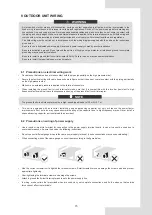
•  Do not install the unit in the following places:

- Where there is mist of mineral oil, oil spray or vapors. Plastic parts may deteriorate, and cause them to come 

loose or water to leak.
- Where corrosive gases (such as sulphurous acid gas) are produced. Where corrosion of copper pipes or soldered 

parts may cause refrigerant to leak.
- Where there is machinery which emits electromagnetic waves. Electromagnetic waves can disturb the control 

system and cause equipment malfunction.
- Where flammable gases may leak, where carbon fiber or ignitable dust is suspended in the air or where volatile 

flammables such as paint thinner or gasoline are handled. These types of gases might cause a fire.
- Where the air contains high levels of salt such as near the ocean.
- Where voltage fluctuates a lot, such as in factories. 
- In vehicles or vessels.
- Where acidic or alkaline vapors are present.

•  This appliance can be used by children 8 years old and above and persons with reduced physical, sensory or 

mental capabilities or lack of experience and knowledge if they are supervised or given instruction on using the 

unit in a safe manner and understand the hazards involved. Children should not play with the unit. Cleaning and 

user maintenance should not be done by children without supervision.

•  Children should be supervised to ensure that they do not play with the appliance.
•  If the supply cord is damaged, it must be replaced by the manufaturer or its service agent or a similarly qualified 

person.

•  DISPOSAL: Do not dispose this product as unsorted municipal waste. Collection of such waste seperatelly for 

special treatment is necessary. Do not dispose of electrical appliances as municipal waste, use seperate collection 

facilities. Contact your local goverment for information regarding the collection systems available. If electrical 

appliances are disposed of in landfills or dumps, hazardous substance can leak into the groudwater and get into 

the food chain, damaging your health and well-being.

•  The  wiring must be performed by professional technicians in accordance with national wiring regulation and this 

circuit diagram. An all-pole disconnection device which has at least 3mm seperation distance in all pole and a 

residualcurrent device(RCD) with the rating not exceeding 30mA shall be incorporated in the fixed wiring according 

to the national rule.

•  Confirm the safety of the installation area ( walls, floors, etc. ) without hidden dangers such as water, electricity, 

and gas.Before wiring/pipes.

•  Before installation , check whether the user's power supply meets the electrical installation requirements of 

unit ( including reliable grounding , leakage , and wire diameter electrical load, etc. ). If the electrical installation 

requirements of the product are not met, the installation of the product is prohibited until the product is rectified.

•  When installing multiple air conditioners in a centralized manner, please confirm the load balance of the three-phase 

power supply, and multiple units are prevented from being assembled into the same phase of the three-phase power 

supply.

•  Product installation should be fixed firmly, Take reinforcement measures, when necessary.

 NOTE

•  About Fluorinated Gasses

- This air-conditioning unit contains fluorinated gasses. For specific information on the type of gas and the amount, 

please refer to the relevant label on the unit itself. Compliance with national gas regulations shall be observed.
- Installation, service, maintenance and repair of this unit must be performed by a certified technician.
- Product uninstallation and recycling must be performed by a certified technician.
- If the system has a leak-detection system installed, it must be checked for leaks at least every 12 months. When 

the unit is checked for leaks, proper record-keeping of all checks is strongly recommended.

Summary of Contents for Aquantia KHPMS-BI Series

Page 1: ...asing our product Before using your unit please read this manual carefully and keep it for future reference INSTALLATION OWNER S MANUAL Aquantia Air Water Heat Pumps KHPMS BI Set Outdoor Unit KHP BI 4...

Page 2: ...ts 09 6 3 Drain hole position 10 6 4 Servicing space requirements 10 7 INSTALLATION THE CONNECTING PIPE 11 7 1 Refrigerant piping 11 7 2 Leakage Detection 12 7 3 Heat insulation 12 7 4 Connecting meth...

Page 3: ...TURN OVER TO CUSTOMER 22 13OPERATION AND PERFORMANCE 24 13 1 Protection equipment 24 13 2 About power cut 24 13 3 Heating capacity 24 13 4 Compressor protection feature 24 13 5 Cooling and heating op...

Page 4: ......

Page 5: ...01 8 10 kW 4 6 kW 8 10 kW 4 6 kW Please remove the hollow plate after installation Electric Control System Refrigerant System Wiring diagram 8 10kW for example...

Page 6: ...sistance of other skilled personnel shall be carried out under the supervision of the person competent in the use of flammable refrigerants DANGER Indicates an imminently hazardous situation which if...

Page 7: ...ks and fire Make sure all wiring is secure Use the specified wires and ensure that terminal connections or wires are protected from water and other adverse external forces Incomplete connection or aff...

Page 8: ...able If electrical appliances are disposed of in landfills or dumps hazardous substance can leak into the groudwater and get into the food chain damaging your health and well being The wiring must be...

Page 9: ...l data manual 1 Water outlet connection pipe assembly 1 Energy label 1 3 BEFORE INSTALLATION Before installation Be sure to confirm the model name and the serial number of the unit Handling 1 Handle t...

Page 10: ...he grips in the fan grills to avoid damage The unit is top heavy Prevent the unit from falling due to improper inclination during handling 4 IMPORTANT INFORMATION FOR THE REFRIGERANT This product has...

Page 11: ...nit can be installed at an even level Places where there is no possibility of flammable gas or product leak The equipment is not intended for use in a potentially explosive atmosphere Places where ser...

Page 12: ...prevent exposure to wind install the unit with its suction side facing the wall Never install the unit at a site where the suction side may be exposed directly to wind To prevent exposure to wind inst...

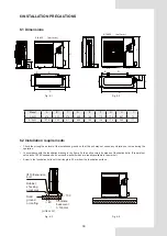
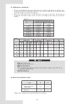
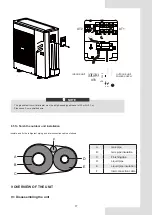
Page 13: ...075 363 411 625 184 126 179 965 117 6 2 Installation requirements Check the strength and level of the installation ground so that the unit may not cause any vibrations or noise during the operation In...

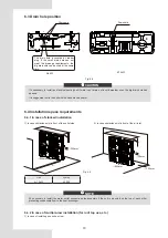
Page 14: ...drain hole has opened It is suggested to site the unit with the base electric heater 6 4 Installation space requirements 6 4 1 In case of stacked installation 1 In case obstacles exist in front of the...

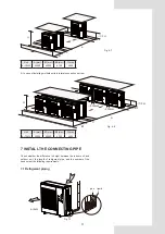
Page 15: ...nstalling multiple units in lateral connection per row Fig 6 8 Unit A mm B1 mm B2 mm C mm 4 10kW 3000 2000 300 600 7 INSTALL THE CONNECTING PIPE Check whether the difference in height between the indo...

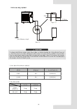
Page 16: ...e while back side getting out pipes 7 2 Leakage Detection Use soap water or leakage detector to check every joint whether leak or not Refer to Fig 7 2 Note A is high pressure side stop valve B is low...

Page 17: ...l difference is greater than 20m it is recommended that an oil return bend with dimensions as specified in Figure 7 4 is set every 5m in the gas pipe of the main pipe and ii if the outdoor unit is bel...

Page 18: ...igh low pressure valves before charging pressured nitrogen Charge pressure nitrogen from the connector on the pressure valves The airtight testing should never use any oxygen flammable gas or poisonou...

Page 19: ...contact with the piping particularly on the high pressure side Make sure no external pressure is applied to the terminal connectors When installing the ground fault circuit interrupter make sure that...

Page 20: ...2 5 10 and 16 1 5 and 2 5 1 5 and 4 16 and 25 2 5 and 4 2 5 and 6 25 and 32 4 and 6 4 and 10 32 and 50 6 and 10 6 and 16 50 and 63 10 and 16 10 and 25 Table 8 2 System Outdoor Unit Power Current Compr...

Page 21: ...igh speed type breaker of 30 mA 0 1 s Please use 3 core shielded wire 8 5 To finish the outdoor unit installation insulate and fix the refrigerant piping and interconnection cable as follows A Gas pip...

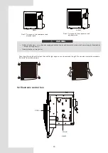
Page 22: ...itch off all power i e unit power supply and backup heater and domestic hot water tank power supply if applicable before removing doors 1 Parts inside the unit may be hot Push the grill to the left un...

Page 23: ...19 PCB A PCB B 8 10kW 9 8 6 4 5 7 1 2 3 NOTE The picture is for reference only please refer to the actual product 9 3 4 10kW units 1 PCB A Inverter module...

Page 24: ...n with hydro box control board CN29 4 Port for IC programming CN32 18 Reserved CN30 5 Port for ground wire CN37 19 Port for communication with PCB A CN17 6 Input port for neutral wire CN10 20 Port for...

Page 25: ...uirements for charge limits in unventilated areas The maximum refrigerant charge in appliance shall be in accordance with the following mmax 2 5 x LFL 5 4 x 1 8 x A 1 2 or the required minium floor ar...

Page 26: ...gerant Indoor unit Room is filled of leakage refrigerant All refrigerant has leaked out 8 10kW Indoor Unit Outdoor Unit Fig 11 2 Fig 11 3 12 TURN OVER TO CUSTOMER The owner s manual of indoor unit and...

Page 27: ...ut below the limit Otherwise oxygen in the room may be affected resulting in a serious accident The refrigerant in the heat pump is safe and normally does not leak If the refrigerant leaks in the room...

Page 28: ...rosting automatically about 2 10 minutes and then water will be drained out from outdoor unit During defrosting the fan motors in the outdoor unit will stop running Never expose little children plants...

Page 29: ...ke the connector dry Add waterproof adhesive 3 The Th sensor failure change a new sensor Discharge temperature sensor Tp error 1 The Tp sensor connector is loosen Re connect it 2 The Tp sensor connect...

Page 30: ...t 2 Pressure sensor failure change a new sensor The main control board PCB B EEprom failure 1 The EEprom parameter is error rewrite the EEprom data 2 EEprom chip part is broken change a new EEprom chi...

Page 31: ...1 The same reason to P1 2 TW_out temp sensor is loosen Reconnect it 3 T1 temp sensor is loosen Reconnect it 4 T5 temp sensor is loosen Reconnect it Module protection 1 Power supply voltage of the uni...

Page 32: ...he power supply 2 If the power supply is OK and check if LED light is OK check the voltage PN if it is 380V the problem usually comes from the main board And if the light is OFF disconnect the power c...

Page 33: ...Fan motor DC motor Horizontal Compressor DC inverter dual rotary Heat exchanger Fin coil Refrigerant Type R32 Quantity 1 55kg 1 65kg Weight Net weight 57kg 67kg Gross weight 68kg 79kg Connections Gas...

Page 34: ...g the period that the work is carried out The ventilation should safely disperse any released refrigerant and preferably expel it externally into the atmosphere 8 Checks to the refrigeration equipment...

Page 35: ...is not a potential source of ignition and is suitable for the refrigerant Leak detection equipment shall be set at a percentage of the LFL of the refrigerant and shall be calibrated to the refrigeran...

Page 36: ...ce or decommissioning it is recommended good practice that all refrigerants are removed safely When tranferring refrigerant into cylinders ensure that only appropriate refrigerant recovery cylinders a...

Page 37: ...Outdoor temperature sensor 2 4 Way Valve 11 Outdoor exchanger sensor 3 Gas liquid separator 12 Stop valve gas 4 Air side heat exchanger 13 Stop valve liquid 5 Electronic expansion Valve 14 High Press...

Page 38: ...E_COOL CHECK NO COM L OUT PCB A Inverter board for 1phase PCB B Main control board for 1phase SW1 SW2 SW3 T3 T4 Tp EEV CN9 XP1 XS2 XP2 CN8 XS1 CN33 SV6 CN5 Th CN1 H_SEN CN4 TF CN14 4 WAY BLUE CN6 BLUE...

Page 39: ...35 16125300002239 V1 0...

Page 40: ......

Reviews: