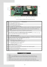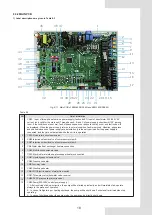
8 OVERVIEW OF THE UNIT
8.1 Main parts of the uint
7 CONNECTION DRAWING OF PIPELINE SYSTEM
Fig.7-1 Connection drawing of pipeline system
This is the water system of standard module.
NOTE
The ratio of the two - way valves on the terminal shall not exceed 50 percent.
NO.
1
2
3
4
5
6
7
NO.
8
9
10
11
12
13
NAME
Air outlet
Top cover
Electric control box
Compressor
Plate heat exchanger
Condenser
Water intlet
NAME
Air inlet
Water outlet
wire controller (It can be placed indoors)
Expansion tank
Gas-liquid separator
Induction pump
Table 8-1
Stop valve
Pressure gauge
Water flow switch
Gate valve
Flexible joint
Y-shaped filter
Thermometer
Circulating pump
Check valve
Automatic discharge valve
Symbol explanation
Auxiliary electric heater
Terminal
Two-way valve
Drain valve
Water charge valve
Plate heat
exchanger
0.15MPa<Water
replenishing pres<0.6MPa
Drain valve
Three-way valve
Drain valve
Differential pressure
by-pass valve
Safety valve
Expansion vessel
Differential pressure
by-pass valve
11
15100103000389


