background image

Pr

oduct Featur

es

 Page 29 

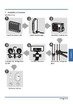
1.  Operation Modes and Functions

1.1  Abbreviation

Unit element abbreviations

Abbreviation

Abbreviation

Element

T1

Indoor room temperature

T2

Coil temperature of evaporator

T3

Coil temperature of condenser

T4

Outdoor ambient temperature

TP

Compressor discharge temperature

Tsc

Adjusted setting temperature

CDIFTEMP

Cooling shutdown temperature

HDIFTEMP2

Heating shutdown temperature

TCDE1

Exit defrost temperature1

TCDE2

Exit defrost temperature2 (maintain 
for a period of time )

TIMING_

DEFROST_TIME

Enter defrost time

In this manual, such as CDIFTEMP, HDIFTEMP2, TCDE1, 
TCDE2, TIMING_DEFROST_TIME...etc., they are  well-
setting parameter of EEPROM.

1.2  Safety Features

Compressor three-minute delay at restart 

Compressor functions are delayed for up to ten seconds 
upon the first startup of the unit, and are delayed for up  
to three minutes upon subsequent unit restarts.

Automatic shutoff based on discharge temperature

If the compressor discharge temperature exceeds a certain 
level for nine seconds, the compressor ceases operation.

Automatic shutoff based on fan speed 

If the indoor fan speed registers below 200RPM or over 
2100RPM for an extended period of time, the unit ceases 
operation 

Inverter module protection 

The inverter module has an automatic shutoff mechanism 
based on the unit’s current, voltage, and temperature. 
If automatic shutoff is initiated, the corresponding error 
code is displayed on the indoor unit and the unit ceases 
operation.

Indoor fan delayed operation

•  When the unit starts, the louver is automatically 

activated and the indoor fan will operate after a period 
of setting time or the louver is in place. 

•  If the unit is in heating mode, the indoor fan is 

regulated by the anti-cold wind function.

Compressor preheating 

Preheating is automatically activated when T4 sensor is 
lower than setting temperature.

Sensor redundancy and automatic shutoff

•  If one temperature sensor malfunctions, the air 

conditioner continues operation and displays the 
corresponding error code, allowing for emergency use.

•  When more than one temperature sensor is 

malfunctioning, the air conditioner ceases operation.

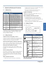
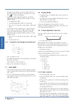
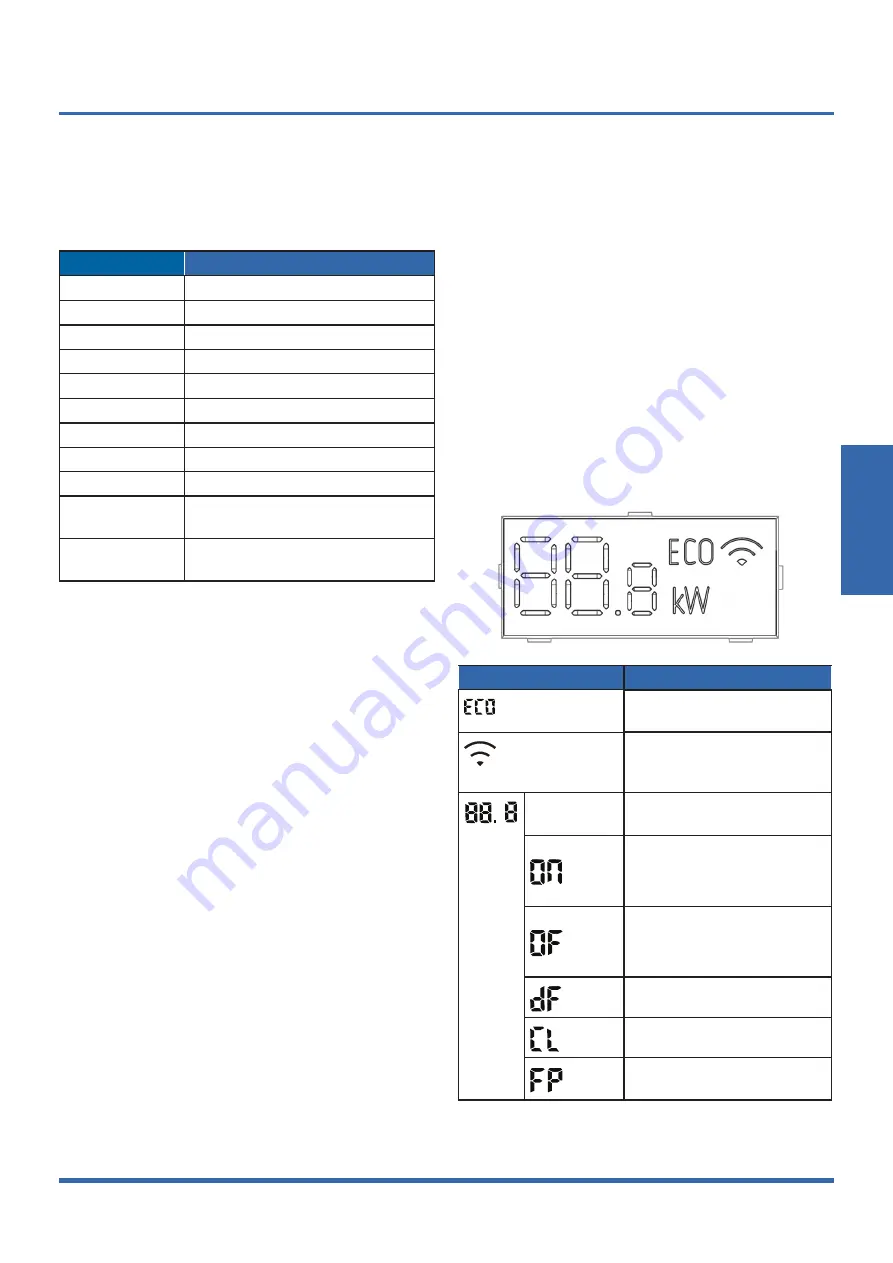
1.3  Display Function

Unit display functions

Display

Function

ECO function (available on 
select units only)
When Wireless Control 
feature is activated (some 
units)

Temperature 
value

Temperature

 (3s) 

Timer ON is set.

Activation of Swing, Boost, 
Silence  or UV-C lamp

 (3s)

Timer OFF is set.

Cancellation of Swing, Boost, 
Silence  or UV-C lamp

Defrost

Active Clean

Heating in room temperature 
under 8°C(46°F)  

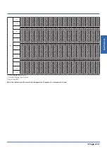
Note: Please select the display function according to 
your purchase product.

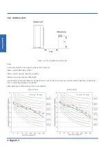
Summary of Contents for KSDA-35 DVR14

Page 1: ...UE 35 DVR13 KSDA 52 DVR14 KSD 52 DR14 KUE 52 DVR13 Double Flow Console TECHNICAL MANUAL Read this manual carefully before installing or operating your new air conditioning unit Make sure to save this...

Page 2: ...ght Difference 10 Noise Criterion Curves 11 Electrical Characteristics 2 Product Features 28 1 Operation Modes and Functions 2 Remote Controller Functions 3 Installation 34 1 Installation Overview 2 L...

Page 3: ...entre of Gravity 10 5 Electrical Wiring Diagrams 11 6 Refrigerant Cycle Diagrams 15 7 Air Velocity and Temperature Distributions 16 8 Capacity Tables 18 9 Capacity Correction Factor for Height Differe...

Page 4: ...following table to determine the specific indoor and outdoor unit model number of your purchased equipment Indoor Unit Model Outdoor Unit Model Capacity Btu h Power Supply KSD 35 DR14 KUE 35 DVR13 12...

Page 5: ...air flow Hi Mi Lo m3 h 650 580 490 780 690 600 Indoor sound pressure level dB A 37 34 27 41 38 32 Indoor sound power level dB A 54 55 Indoor unit Dimension W D H mm 794x206x621 794x206x621 Packing W D...

Page 6: ...d quantity Kg 0 71 1 15 Design pressure MPa 4 3 1 7 4 3 1 7 Refrigerant piping Liquid side Gas side mm inch 6 35 9 52 1 4 3 8 6 35 12 7 1 4 1 2 Max refrigerant pipe length m 25 30 Max difference in le...

Page 7: ...Specifications Page 7 3 Dimensional Drawings 3 1 Indoor Unit...

Page 8: ...Specifications Page 8 3 2 Outdoor Unit KUE 35 DVR13...

Page 9: ...Specifications Page 9 KUE 52 DVR13...

Page 10: ...Specifications Page 10 4 Centre of Gravity KUE 35 DVR13 KUE 52 DVR13...

Page 11: ...nit Abbreviation Paraphrase Y G Yellow Green Conductor CAP1 Indoor Fan Capacitor FAN Indoor Fan PUMP PUMP L LIVE N NEUTRAL TO CCM Comm Bus Central Controller T1 Indoor Room Temperature T2 Coil Tempera...

Page 12: ...e controller To Remote Contol To Remote Alarm 3 YELLOW WHITE Y G RED N_IN BLACK INDOOR UNIT OUTDOOR UNIT 1 L 2 N L_IN S CN12CN42 INDOOR FAN2 M CN23 CN19 CN81 PLASMA LOWER OUTLET SWING MOTOR CN15 2 5 5...

Page 13: ...COMP Compressor L PRO K2 Low Pressure Switch Shorting Stub K1 High Pressure Switch Shorting Stub TRANS Power Transformer T4 10K RESISTANCE Outdoor Ambient Temperature T3 10K RESISTANCE Coil Temperatu...

Page 14: ...Specifications Page 14 KUE 35 DVR13 KUE 52 DVR13...

Page 15: ...le Diagrams Model Pipe Size Diameter mm inch Piping length m ft Elevation m ft Additional Refrigerant Gas Liquid Rated Max Rated Max 12k 9 52 3 8 6 35 1 4 5 16 4 25 82 0 10 32 8 12g m 0 13oz ft 18k 12...

Page 16: ...Specifications Page 16 7 Air Velocity and Temperature Distributions Discharge Angle 70 Upper 0 Lower Cooling airflow velocity distributions Cooling temperature distributions...

Page 17: ...Specifications Page 17 Discharge Angle 20 Upper 0 Lower Heating airflow velocity distributions Heating temperature distributions...

Page 18: ...90 3 90 3 90 4 19 4 19 4 19 4 19 S T 0 73 0 83 0 92 1 00 0 59 0 67 0 76 0 85 0 52 0 60 0 69 0 77 0 36 0 44 0 52 0 60 PI 0 70 0 70 0 70 0 70 0 69 0 69 0 69 0 69 0 69 0 69 0 69 0 69 0 69 0 69 0 69 0 69...

Page 19: ...31 1 31 1 32 1 32 1 32 1 32 650 15 TC 3 84 3 87 3 90 3 93 4 02 4 02 4 02 4 05 4 12 4 12 4 12 4 12 4 40 4 40 4 40 4 40 S T 0 77 0 88 1 00 1 00 0 60 0 70 0 81 0 98 0 51 0 62 0 72 0 83 0 33 0 42 0 52 0 6...

Page 20: ...22 4 22 4 22 4 22 S T 0 78 0 89 1 00 1 00 0 61 0 72 0 82 0 93 0 53 0 63 0 74 0 84 0 34 0 44 0 53 0 63 PI 1 90 1 90 1 90 1 90 1 91 1 91 1 91 1 91 1 91 1 91 1 91 1 91 1 93 1 93 1 93 1 93 690 15 TC 5 35...

Page 21: ...08 1 08 1 09 1 09 1 09 1 09 20 TC 5 18 5 18 5 24 5 30 5 50 5 50 5 50 5 50 5 64 5 64 5 64 5 64 6 08 6 08 6 08 6 08 S T 0 75 0 85 0 95 1 00 0 59 0 69 0 79 0 88 0 52 0 61 0 71 0 80 0 35 0 44 0 52 0 61 PI...

Page 22: ...7 0 3 17 3 14 3 12 3 12 1 36 1 41 1 38 1 38 5 6 3 21 3 18 3 16 3 16 1 32 1 33 1 33 1 34 2 8 3 24 3 21 3 18 3 18 1 24 1 25 1 25 1 26 0 0 3 24 3 21 3 18 3 16 1 18 1 18 1 18 1 18 2 8 3 36 3 30 3 27 3 27...

Page 23: ...89 4 86 4 84 4 81 1 79 1 85 1 83 1 84 5 6 4 87 4 84 4 81 4 78 1 75 1 77 1 78 1 79 2 8 4 84 4 78 4 75 4 75 1 68 1 70 1 70 1 71 0 0 4 75 4 69 4 66 4 63 1 60 1 62 1 62 1 63 2 8 4 81 4 75 4 72 4 69 1 54...

Page 24: ...8 0 970 0 1 000 0 993 0 978 0 970 Outdoor Upper than Indoor 5 0 992 0 985 0 970 0 962 10 0 977 0 962 0 955 Capacity Btu h 18K Pipe Length m Cooling 5 10 20 30 Height difference H m Indoor Upper than O...

Page 25: ...lid at free field condition Data is valid at nominal operation condition Reference acoustic pressure OdB 20 Pa Sound level will vary depending on a range of factors such as theconstruction acousticabs...

Page 26: ...at free field condition Data is valid at nominal operation condition Reference acoustic pressure OdB 20 Pa Sound level will vary depending on arrange off actors such as the construction acoustic absor...

Page 27: ...40V 50Hz 220 240V 50Hz Power Wiring mm2 3 1 5 3 2 5 Circuit Breaker Fuse A 20 16 20 16 Indoor Outdoor Connecting Wiring Weak Electric Signal mm2 Strong Electric Signal mm2 4 1 0 4x2 5 with auxiliary e...

Page 28: ...1 6 Heating Mode Heat pump models 30 1 7 Auto Mode 32 1 8 Drying Mode 32 1 9 Forced operation Function 32 1 10 Timer Function 32 1 11 Sleep Function 32 1 12 Auto Restart 33 1 13 8 C Heating 33 1 14 F...

Page 29: ...operation Inverter module protection The inverter module has an automatic shutoff mechanism based on the unit s current voltage and temperature If automatic shutoff is initiated the corresponding err...

Page 30: ...protective time Compressor running frequency is more than test frequency When compressor running frequency is equal to test frequency T4 is more than 15 C or T4 fault Change setting temperature Turbo...

Page 31: ...pressor to cease operations 1 6 2 Indoor Fan Control 1 In heating mode the indoor fan operates continuously The fan speed can be set to 1 100 or low medium high and auto Anti cold air function The ind...

Page 32: ...ing mode All protections are activated and operate the same as they do that in cooling mode Low Room Temperature Protection If the room temperature is lower than 10 C the compressor ceases operations...

Page 33: ...not receive a signal for 7 minutes or you press Follow Me the function turns off The unit regulates temperature based on its own sensor and settings 1 15 Silence Press Silence on the remote control t...

Page 34: ...stallation 39 4 Outdoor Unit Installation 41 5 Drainage Pipe Installation 42 6 Refrigerant Pipe Installation 43 7 Vacuum Drying and Leakage Checking 44 8 Additional Refrigerant Charge 45 9 Engineering...

Page 35: ...ion sheath some models 2 Heat insulation pipe 1 Anchor 6 depending on models Mounting plate fixing screw 6 depending on models Copper nut 2 Hook 2 Drain joint some models 1 Seal ring some models 1 Mag...

Page 36: ...alled on the outdoor unit 1 on some models Transfer connector 9 52 12 7 0 375in 0 5in Packed with the indoor unit NOTE Pipe size may differ from appliance to appliance To meet different pipe size requ...

Page 37: ...llation Overview Installation Order Install the drainpipe Install the outdoor unit 1 2 3 4 5 MC MC 6 7 Install the indoor unit Evacuate the refrigeration system Connect the wires Connect the refrigera...

Page 38: ...tight rooms Be sure to keep the unit unobstructed in at least two of the three directions M N P 2 4 Rows of series installation The relations between H A and L are as follows L A L H L 1 2H 25 cm 9 8...

Page 39: ...ions it is not necessary 2 Fix the mounting plate with a tapping screw onto the wall NOTE It is recommended to fx it on the wall according to the hanging hole indicated by the arrow on the mounting pl...

Page 40: ...pipe 1 Open the bottom piping cover plate Press and hold the bottom two buckles and then rotate to open the piping cover plate Two buckles 2 Remove the cover plate Remove the pipe cover plate and inst...

Page 41: ...vity center of the unit is not at its physical center so please be careful when lifting it with a sling Never hold the inlet of the outdoor unit to prevent it from deforming Do not touch the fan with...

Page 42: ...for reference PVC pipe Reference value of inner diameter of pipe mm Allowable maximum water flowrate l h Remark Slope 1 50 Slope 1 100 PVC25 20 39 27 For branch pipe PVC32 25 70 50 PVC40 31 125 88 Co...

Page 43: ...act with ground directly 5 3 Insulation work of drainage pipe Refer the introduction to the insulation engineering parts 6 Refrigerant Pipe Installation 6 1 Maximum length and drop height Ensure that...

Page 44: ...dinary vacuum drying 1 When conduct first vacuum drying connect pressure gauge to the infusing mouth of gas pipe and liquid pipe 4 Cut the selected pipe with pipe cutter Make the section flat and smoo...

Page 45: ...lf an hour If the pressure reached 755mmHg start to pressure leakage test If it cannot reached the value repeat vacuum damage and vacuum drying again for 1 hour 4 Leakage test After the vacuum degree...

Page 46: ...ipe shall be 5 10cm longer than the gap of the insulation mate rial The insulation material at the joint pipe shall be inserted into the gap of the insulation material The insulation material at the j...

Page 47: ...10 1 10 16 1 5 16 25 2 5 25 32 4 32 45 6 11 Test Operation 11 1 The test operation must be carried out after the entire installation has been completed 11 2 Please confirm the following points before...

Page 48: ...rn on the main power switch and run the air conditioner in COOL mode d Listen to the sound of the drain pump to see if it makes any unusual noises e Check to see that the water is discharged It may ta...

Page 49: ......

Reviews: