


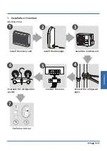


Installation
Page 44
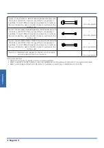
•
Be sure to use two spanners and proper torque to
fasten the nut, too large torque will damage the
bellmouthing, and too small torque may cause
leakage. Refer the following table for different pipe
connection.
Pipe Diameter
Torque
Sketch map
N.
m(lb.ft)
1/4" (6.35)
18~20
(13.3~14.8)
3/8" (9.52)
32~39
(23.6~28.8)
1/2" (12.7)
49~59
(36.1~43.5)
5/8" (15.9)
57~71
(42~52.4)
3/4" (19)
67~101
(49.4~74.5)
7/8" (22)
85-110
(62.7-81.1)
7. Vacuum Drying and Leakage
Checking
7.1 Purpose of vacuum drying
•
Eliminating moisture in system to prevent the phe-
nomena of ice-blockage and copper oxidation
.
Ice-blockage shall cause abnormal operation of
system, while copper oxide shall damage
compressor.
•
Eliminating the non-condensable gas (air) in system
to prevent the components oxidizing, pressure fluc-
tuation and bad heat exchange during the operation
of system.
7.2 Selection of vacuum pump
•
The ultimate vacuum degree of vacuum pump shall
be -756mmHg or above.
•
Precision of vacuum pump shall reach 0.02mmHg or
above.
7.3 Operation procedure for vacuum
drying
Due to different construction environment, two kinds of
vacuum drying ways could be chosen, namely ordinary
vacuum drying and special vacuum drying.
7.3.1 Ordinary vacuum drying
1.
When conduct first vacuum drying, connect pressure
gauge to the infusing mouth of gas pipe and liquid pipe,
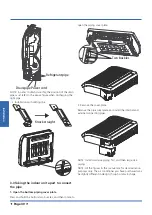
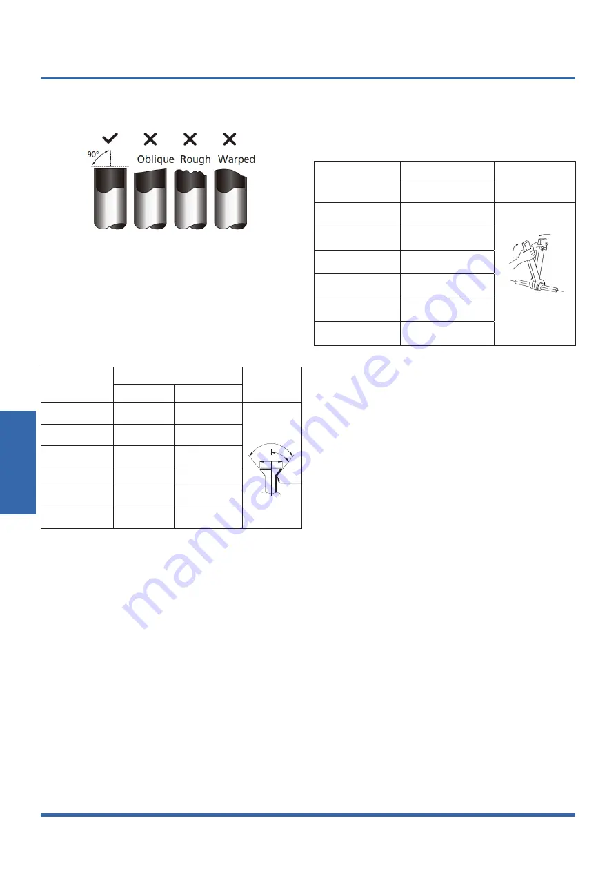
4.Cut the selected pipe with pipe cutter
•
Make the section flat and smooth.
5. Insulate the copper pipe
•
Before test operation, the joint parts should not be
heat insulated.
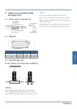
6. Flare the pipe
•
Insert a flare nut into the pipe before flaring the
pipe
•
According to the following table to flare the pipe.
Pipe diameter
(inch(mm))
Flare dimension A (mm/inch)
Flare shape
Min
Max
1/4" (6.35)
8.4/0.33
8.7/0.34
R0.4~0.8
45
2
90
4
A
3/8" (9.52)
13.2/0.52
13.5/0.53
1/2" (12.7)
16.2/0.64
16.5/0.65
5/8" (15.9)
19.2/0.76
19.7/0.78
3/4" (19)
23.2/0.91
23.7/0.93
7/8" (22)
26.4/1.04
26.9/1.06
•
After flared the pipe, the opening part must be seal
by end cover or adhesive tape to avoid duct or exog-
enous impurity come into the pipe.
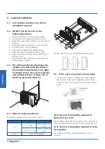
7. Drill holes if the pipes need to pass the wall.
8. According to the field condition to bend the pipes so
that it can pass the wall smoothly.
9. Bind and wrap the wire together with the insulated pipe
if necessary.
10. Set the wall conduit
11. Set the supporter for the pipe.
12. Locate the pipe and fix it by supporter
•
For horizontal refrigerant pipe, the distance be-
tween supporters should not be exceed 1m.
•
For vertical refrigerant pipe, the distance between
supporters should not be exceed 1.5m.
13. Connect the pipe to indoor unit and outdoor unit by
using two spanners.
Summary of Contents for KSDA-35 DVR14
Page 7: ...Specifications Page 7 3 Dimensional Drawings 3 1 Indoor Unit...
Page 8: ...Specifications Page 8 3 2 Outdoor Unit KUE 35 DVR13...
Page 9: ...Specifications Page 9 KUE 52 DVR13...
Page 10: ...Specifications Page 10 4 Centre of Gravity KUE 35 DVR13 KUE 52 DVR13...
Page 14: ...Specifications Page 14 KUE 35 DVR13 KUE 52 DVR13...
Page 49: ......


