background image

26

When the air conditioner is installed in a small 

room, take appropriate measures to ensure 

that the concentration of refrigerant leakage 

occurring in the room does not exceed the 

critical level.
Install the air conditioner securely in a location 

where the base can sustain the weight 

adequately.
Perform the specified installation work to 

guard against an earthquake.
If the air conditioner is not installed 

appropriately, the unit could fall and cause an 

accident.
If refrigerant gas has leaked during installation, 

ventilate the room immediately.
If the leaked refrigerant gas comes into contact 

with fire, noxious gas may be generated.
After the installation work, confirm that 

refrigerant gas does not leak.
If refrigerant gas leaks into the room and flows 

near a source of flame, such as a cooking 

range, noxious gas might be generated.
Electrical work must be performed by a 

qualified electrician in accordance with the 

installation manual. Make sure the air 

conditioner uses a dedicated power supply.
An insufficient power supply capacity or 

inappropriate installation may cause fire.
Use the specified cables for wiring to connect 

the terminals securely, and to prevent external 

forces applied to the terminals from affecting 

the terminals.

6) Reamer
7) Gas leak detector
8) Tape measure
9) Thermometer
10) Mega-tester
11) Electro circuit tester
12) Hexagonal wrench
13) Flare tool
14) Pipe bender

Required tools for installation work

1) Philips screw driver
2) Hole core drill (65mm)
3) Spanner
4) Pipe cutter
5) Knife

Equipment complying with IEC 61000-3-12.

Be sure to provide grounding.

Do not connect ground wires to gas pipes, water pipes, 
lightning rods or ground wires for telephone cables.

Conform to the regulations of the local electric 

company when 

wiring the power supply.

Inappropriate grounding may cause electric shock.

Do not install the air conditioner in a location 

subject to a risk 

of exposure to a combustible gas.

If a combustible gas leaks, and stays around the unit, a 
fire may occur.

15) Level vial
16) Metal saw
17) Gauge manifold (Charge hose: R32 special

requirement)
18) Vacuum pump (Charge hose: R32 special

requirement)
19) Torque wrench

1/4 (6.4 mm) 14.2-17.2 N·m (144-176 kgf·cm)

         3/8 (9.5 mm) 32.7-39.9 N·m (333-407 kgf·cm)

         1/2 (12.7 mm) 49.5-60.3 N·m (504-616 kgf·cm)

         5/8 (15.9 mm) 61.8-75.4 N·m (630-770 kgf·cm)
20) Copper pipe gauge adjusting projection margin
21) Vacuum pump adapter

2. PACKING BOX

2.1 Delivery and Moving

Delivery 

Remember the following:

At the time of delivery, check the unit for any damage. 

Report any damage immediately to the carrier's claim 

agent.
As far as possible, transport the packaged unit to its 

final installation site to prevent damage during the 

handling process.
Take note of the following items when transporting the 

unit:

Since the gravity center of the unit is not at its 

physical center, please be careful when lifting it 

with a sling.
Never hold the inlet of the outdoor unit to prevent it 

from deforming.

Select the unit transportation path in advance.

Keep the unit with its front facing upwards so as 

not to damage it.

Fragile. Handle with care.

Moving 

Do not touch the fan with your hands or other objects.

Do not lean the unit more than 45°, and do not lay it on 

its side.

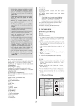
QUANTITY

APPEARANCE

NAME

1. Outdoor unit 

operation and 

installation manual

1

1

2. Water outlet

pipe connector

3.Magnetic ring

(Only for

single-phase units)

1

4.Build-out resistor

1

Table 2-1

INSTALLA
TION  
FITTINGS

2.2 Attached Fittings

Summary of Contents for Mini Amazon KMF-180 DTR6

Page 1: ...ng your air conditioner please read this manual carefully and retain it for future reference The figures shown in this manual are for reference purposes only and may be slightly different from the act...

Page 2: ...6 35 OUTDOOR UNIT INSTALLATION ELECTRICAL WIRING 46 8 9 25 1 2 16 17 19 01 48 COMMISSIONING CONFIGURATION PRECAUTIONS ON REFRIGERANT LEAKAGE 10 49 TURN OVER TO CUSTOMER 11 50 TECHNICAL DATA INSTALLATI...

Page 3: ...12 The figures in this manual are for explanation purposes only They may be slightly different from the air conditioner you purchased depending on the model The actual shape shall prevail Refrigerant...

Page 4: ...e the following instructions must be followed Ignoring these instructions may cause harm or damage The safety precautions listed here are divided into the following types They are quite important so b...

Page 5: ...ng the refrigerating system comply with the following precautions prior to conducting work on the system shall be undertaken according to controlled procedures so as to minimize the risk of the presen...

Page 6: ...ts only with parts specified by the manufacturer Other parts may result in the ignition of refrigerant which has leaked into the surroundings Check that cabling will not be subject to wear corrosion e...

Page 7: ...en confirmed as complying to corresponding partial unit requirements of this International Standard Ensure that contamination of different refrigerants does not occur when using charging equipment Hos...

Page 8: ...ditioner when using a room fumigation type insecticide Failure to observe this precaution could cause the chemicals to become deposited in the unit which could endanger the health of those who are hyp...

Page 9: ...ments 1 3 1 2 Piping installation requirements Low temperature solder alloys such as lead tin alloys are not acceptable for pipe connections Reusable mechanical connectors and flared joints are not al...

Page 10: ...hall be protected or enclosed to avoid damage Equipment pipes in the occupied space in question must be installed in such a way that it is protected against accidental damage The system uses R32 refri...

Page 11: ...for systems needing additional refrigerant charge and which will limit room area strategy Similarly the total amount of refrigerant in the system shall be less than or equal to the maximum refrigerant...

Page 12: ...evel opening The opening shall not be less than 0 0123 m2 Anvmin The area of any openings above 300 mm from the floor shall not be considered in determining compliance with Anvmin At least 50 of the o...

Page 13: ...2 00 4 00 6 00 8 00 10 00 12 00 Minimum room area Amin m2 a Installation height 1 b Installation height 2 c With incorporated circulation airflow for the installation height 1 d With incorporated circ...

Page 14: ...2 12 7 626 9 321 12 12 7 695 9 405 12 12 7 763 9 489 12 12 7 831 9 571 12 12 7 898 9 654 12 12 7 965 9 735 12 12 8 031 9 816 12 12 8 097 9 896 12 12 8 162 9 975 12 12 8 226 10 054 12 12 8 29 10 133 12...

Page 15: ...ight At least one alarm device shall be installed inside each occupied space For the occupancy listed below the alarm system shall also warn at a supervised location such as the night porter s locatio...

Page 16: ...ound floor b The IDU installation height is not less than 2 2 m while A is 14m2 and on the lowest underground floor c The refrigerant charge limitation is on the lowest underground floor while A is 14...

Page 17: ...arge Mmax in the system from the above room area limitations 2 The maximum refrigerant charge Mmax with air duct system or additional measures such as areas with mechanical ventilation 3 12 kg from th...

Page 18: ...the smallest room meets the requirements Calculate the total refrigerant charging amount Mc according to section 5 8 1 Check the corresponding table to get the maximum refrigerant charge Mmax Yes 1 S...

Page 19: ...may be triggered and the air conditioner may malfunction When the unit operates in cooling mode in a relatively humid environment relative humidity higher than 80 condensation may occur on the surface...

Page 20: ...in the following circumstances Cooling Heating Mishandling in operation When the breaker was broken do not use any unspecified breaker or other wire to replace the original breaker The use of electri...

Page 21: ...n it accidentally leaks and comes into contact with flammable substances generated by existing heaters and burning devices in the room Qualified maintenance personnel must verify that the point of lea...

Page 22: ...r to shade the unit from sunshine Reduce heat source AC cooling capacity is reduced normal Check for leakage and correctly recharge refrigerant Causes Power failure Power breaker is off Batteries of t...

Page 23: ...cated on the display When the set time is reached the air conditioner will automatically start and the appropriate indicator will go off Check whether the signal transmitter of the remote controller i...

Page 24: ...T4 error open short Refrigerant leakage sensor error Plate heat exchanger outlet temperature sensor T6B error open short Outdoor heat exchanger temperature sensor T3 error open short Inverter module...

Page 25: ...Technology barrier U02 U12 U21 U31 U32 U33 U34 U35 U37 U3b U3C U41 U3A U38 Compressor high DC bus current protection 1P32 protection occurs 3 times in 100 minutes High AC voltage protection Low AC vol...

Page 26: ...exceeds the upper limit in Cooling mode Outdoor ambient temperature exceeds the lower limit in Cooling mode Refrigerant judgment no result Refrigerant quantity judgment Significantly excessive Refrige...

Page 27: ...em switches over to heating operation after defrost operation moisture generated by defrosting becomes steam and is exhausted A continuous low shah sound is heard when the system is in cooling operati...

Page 28: ...or a similarly qualified person in order to avoid creating a hazard An all pole disconnection switch which has a contact separation of at least 3 mm in all poles should be connected using fixed wirin...

Page 29: ...es water pipes lightning rods or ground wires for telephone cables Conform to the regulations of the local electric company when wiring the power supply Inappropriate grounding may cause electric shoc...

Page 30: ...to low speed The heating capacity of the system decreases as the ambient outdoor temperature decreases In areas where the design heating temperature of the air conditioner is 5 C and the unit needs t...

Page 31: ...ry of a building ensure normal fan operation by using a duct or a wind shield Figure 4 1 Strong wind Strong wind 4 1 2 Installation space Unit mm B A G Figure 4 2 D C I H F E Table 4 1 unit mm Model A...

Page 32: ...uality of the installation seal The piping and other pressure vessels must comply with the applicable laws and be suitable for use with the refrigerant Use only phosphoric acid deoxidized seamless cop...

Page 33: ...HN 01D Gas pipe Liquid pipe 15 9 15 9 19 1 9 52 9 52 9 52 A 63 63 A 160 160 A 280 Branch joint kit Table 4 6 Table 4 7 Indoor unit auxiliary pipe a f Indoor unit capacity 100 W Indoor unit pipe size m...

Page 34: ...6 kW Referring to Table 4 6 the gas and liquid pipe size of L2 are 12 7 and 6 35 respectively and the branch joint B is FQZHN 01D Similarly the pipe size of L3 is 15 9 and 9 52 the pipe size of L3 and...

Page 35: ...ng provided on site Gas side piping provided on site Liquid side piping provided on site Liquid side piping provided on site Liquid side piping provided on site Side outlet connection mode Outlet pipi...

Page 36: ...The leakage must be checked and solved and the test should be performed again Under no circumstances shall potential sources of ignition be used to search for or detect refrigerant leaks A halide tor...

Page 37: ...The total refrigerant charge of the system including factory charge and additional charge must not exceed the maximum design refrigerant charge of 12 kg WARNING Make sure all connected indoor units ha...

Page 38: ...units the maximum allowable voltage range variation between phases is 2 3 Select a circuit breaker that has a contact separation in all poles not less than 3 mm providing full disconnection where MFA...

Page 39: ...the communication terminal block Otherwise the whole system may fail You must first connect the earth line note that you should use only the yellow green wire to connect to the earth and you must turn...

Page 40: ...tion mode of IDU and ODU Table 6 3 communication mode X Y E P Q E M1 M2 O A H1 H2 Controller PQE IDU Comm HyperLink IDU Comm Digital PowerMeter Communication terminal Figure 6 5 6 3 Connecting the Com...

Page 41: ...55014 1 and EN 55014 2 The communication line must be shielded wire Figure 6 6 Figure 6 7 HyperLink M1 M2 communication Keep the power on off for all IDUs Do not connect the HyperLink M1 M2 communicat...

Page 42: ...are optional accessories Please contact the local dealer for purchase if needed Applicable standards EN 55014 1 and EN 55014 2 The communication line must be shielded wire Digital Power Meter O A Refr...

Page 43: ...Function of buttons SW3 to SW6 7 2 3 Menu mode Outdoor unit state Parameters displayed on DSP1 Parameters displayed on DSP2 Standby Unit s address The number of indoor units in communication with the...

Page 44: ...unit address Automatic priority mode Cooling priority mode VIP indoor unit voting priority mode In response to heating mode only In response to cooling mode only Heating priority mode Change over Voti...

Page 45: ...and outdoor unit 40m level difference between indoor unit and outdoor unit 50m level difference between indoor unit and outdoor unit Normal High sensible heat mode Low temperature mode Network address...

Page 46: ...Condensation temperature setting Kc0 51 Non stop compressor defrosting Stop compressor defrosting Self cleaning unavailable Self cleaning available Refrigerant shut off device unavailable Refrigerant...

Page 47: ...VC position Reserved High pressure of unit Low pressure of unit Quantity of online IDUs Quantity of running IDUs 0 1 2 3 4 5 6 7 8 9 10 11 12 13 14 15 16 17 18 19 20 21 22 23 24 25 26 27 28 29 30 31 3...

Page 48: ...eserved 3 D2 Reserved 4 E1 Evaporator 5 F1 Reserved 6 F2 Reserved 0 Not in special mode 1 Oil return 2 Defrost 3 Startup 4 Stop 5 Quick check 6 Self cleaning 0 5 5 represents the most silent 0 0Pa 1 1...

Page 49: ...the relevant regulations make sure the field wiring is based on the instructions described in section 6 2 and 6 3 on connecting wires Earth line Make sure the earth line is connected correctly and th...

Page 50: ...n If the IDUS and ODU are connected by M1M2 communication please set the 4th digit of the ODU digital display to 2 Once the communication protocol has been set short press the OK button to confirm and...

Page 51: ...nterface should be connected to facilitate the operations of the indoor unit Please refer to the installation manual of the indoor unit for more details INFORMATION i Refer to the installation manual...

Page 52: ...three months or where a leakage detection system is installed at least every six months 4 Non hermetically sealed equipment charged with fluorinated greenhouse gases shall only be sold to the end use...

Page 53: ...rator 1 2 3 4 5 6 7 8 9 10 11 12 13 14 15 Legend Heat exchanger pipe temperature sensor Outdoor ambient temperature sensor Liquid pipe temperature sensor Plate heat exchanger outlet temperature sensor...

Page 54: ...1 12 13 14 15 EXVA O S INV1 T7C1 GLQ1 GLQ4 ACC PL T71 EXVC T5 GLQ2 T6B TL ST1 T8 T3 GLQ3 Liquid Stop Valve Gas Stop Valve DXF1 PH T4 HPS M 2 4 5 6 7 8 9 10 11 12 13 14 15 3 1 Legend Heat exchanger pip...

Page 55: ...52 11 2 Fan Performance 0 5 10 15 20 25 30 35 40 45 4500 5000 5500 6000 6500 External static pressure Pa Air flow m3 h 0Pa 10Pa 5500 rated 20Pa 30Pa 35Pa 18kW unit fan performance Figure 11 9...

Page 56: ...Tj 25 C Tj 20 C Off mode Thermosat off mode Crankcase heater mode Standby mode PCK PSB Pdc Pdc Pdc Pdc 17 50 12 63 8 15 4 41 kW kW kW kW kW kW kW kW Tj 35 C Tj 30 C Tj 25 C Tj 20 C EERd EERd EERd EER...

Page 57: ...C COPd COPd COPd COPd 2 77 4 64 6 68 9 33 Information requirements for heat pumps Tbiv bivalent temperature Pdh 11 00 kW kW Pdh Tbiv 11 00 2 34 2 34 TOL operation temperature Tbiv bivalent temperatur...

Page 58: ...55...

Page 59: ...16127000004490 V D...

Page 60: ......

Reviews: